I want to integrate my new Viessmann Vitovalor 300-P fuel cell heating into my home automation. For this, I use the Optolink interface, vcontrold from the openv community, and create my own configuration files from several sources.
If you want to skip the introduction bla-bla, you may directly go to
- Building the OptoLink connector
- Setting up vcontrold on a Raspberry Pi
- The Vitovalor-specific XML configuration files
Disclaimer: Interfacing with your heating system as described here is happening at your own risk! There is no official support for this by Viessmann, and the methods shown here may potentially damage your device!
My New Fuel Cell Heating
Since a few weeks its in my cellar: A brand new heating that sports a fuel cell module! Top notch!  Its a Vitovalor 300-P by Viessmann. And of course I want to integrate this into my home automation! The heating comes with a LAN interface which connects it to Viessmann’s cloud service. This already allows me to use a smartphone to control the heating from abroad, and also offers a very detailed glance into every system parameter and measurement from the vitodata-website (very cool!), but there is no API to use for my own interfacing and purposes.
However, the heating features an OptoLink interface, which is basically an infrared (860 nm receiver, 880 nm sender) serial interface with a standard UART, using 4800 baud, 8bits, even parity and two stop bits with no handshake (4800,8,E,2). And since this is kind of a standard interface for nearly any Viessman heating since at least a decade, other enthusiasts have already done all the hard work to figure out how to interface with such heatings – mainly the openv project (mostly in German – sorry). Many, many thanks for their efforts and the great wiki pages and software!
There exists a simple and cheap circuit for interfacing with Raspberry Pi’s UART, and the vcontrold daemon that does all the communication with the heating, providing a concise command line interface via telnet for access from other programs. Really good work!
So, what remains to be done? Well, while OptoLink is kind of established, each and every Viessmann heating speaks its own dialect. vcontrold accepts an XML file that defines all commands the individual heating model understands; and here’s my todo: I need to work out the specifics of Vitovalor 300-P with its Vitotronic 200 RF HO1E control unit. Many commands are identical across a lot of heatings, but others are behaving differently for each model or exist just for one or a few models.
But first:
Building the OptoLink Connector
You can of course buy an original Viessmann Optolink cable, which does include an UART to USB bridge, but that sets you back by about 60 € – and where’s the fun? So I decided to build one myself, following the instructions for the Raspberry Pi UART interface from openv.
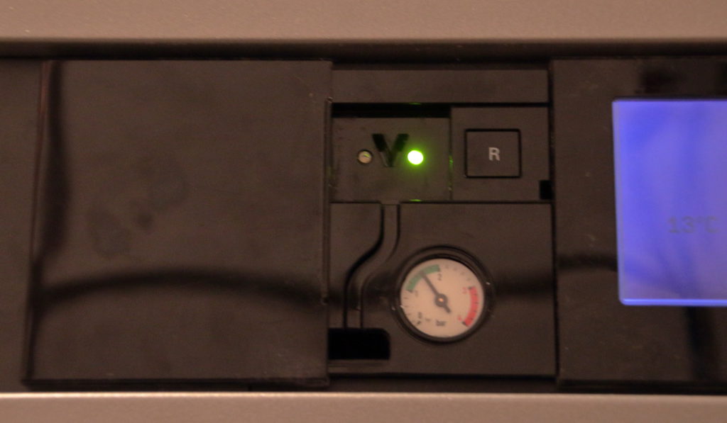
There is mainly one challange when building your own interface: The “V”. The V-shaped gap between sender and receiver is the only mechanical reference, and the original cable has a matching V-shaped protrusion to fit into the gap (Click here for an image of the original cable and the V shaped protrusion). Of course the best way would to 3D-print your own (and people have), but since I lack a 3D printer, I had to get creative.

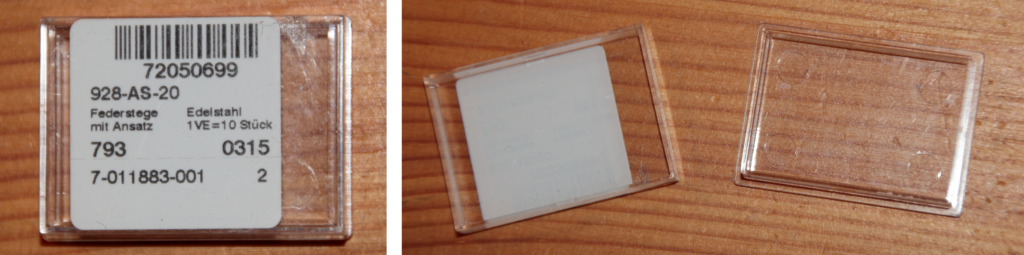
First, I was lucky to find a plastic housing that nearly perfectly fit into the rectangular hole in front of the interface: A box that contained spring bars for wrist watches. It measures about 24 × 36 × 6 mm, which is slightly too broad, so you’ve to cut away the left and right flank. Perhaps you can find one at your local watchmakers or jewelers shop if you face the same task.
The transparant housing allowed to use a permanent marker to copy the V shape onto the plastic. Along these lines, I applied hot glue (several layers – 3D printing for the poor ), which then, using a sharp paper knife, I cut into the required V shape. Worked nicely on first try! The plastic gets rather scratched, but who cares…

Next, the openv article warns you that, if not properly shielded, there may be cross-talk between sender and receiver. So I added heat shrink tube to the holes for the receiver and sender, fixating it with superglue (The image only shows one hole covered, but the second also received shrink tube. In the image you can also see the cut away flanks of the box that otherwise would make it too broad to fit).
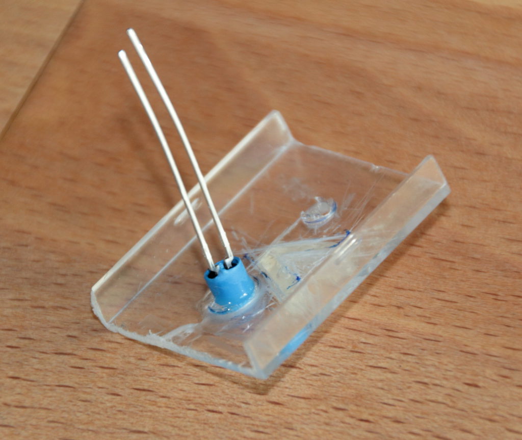
Openv strongly suggests a specific type of photo transistor and IR emitter diode, since others had problems with stray light or insufficient light transmission. While I was able to get the exact photo transistor, the IR LED is out of production. I searched for an IR LED with similar optical characteristics, and found IRL 81 A, wich as a side effect is much easier to fit into the confined space due to its form factor (click here for an image).
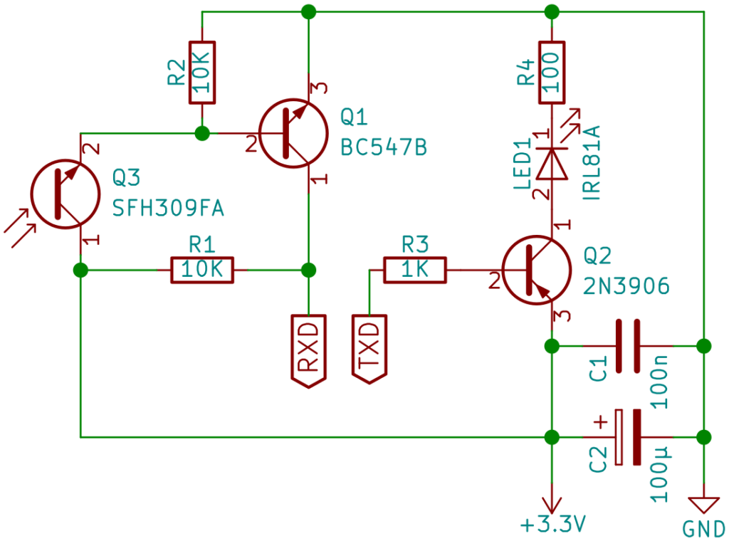
This LED requires a slightly different resistor. Also, because I had some issues due to the very long cable (about 10 m) I attached, I reduced the base resistor at the LED driver. So, here’s the part list and approximate cost:
Parts list
| 2 | 10 kΩ resistor | 0.01 € | |
| 1 | 1 kΩ resistor | 0.01 € | Instead of one 10 kΩ resistor in the original design |
| 1 | 100 Ω resistor | 0.01 € | Instead of 180 Ω resistor in original design |
| 1 | BC547B transistor | 0.20 € | |
| 1 | 2N3906 transistor | 0.05 € | |
| 1 | IRL 81 A infrared LED | 0.60 € | As replacement for the original SFH487-2 |
| 1 | SFH 309 FA infrared photo transistor | 0.25 € | |
| 1 | 100 nF capacitor | 0.05 € | |
| 1 | 100 μF electrolytic capacitor | 0.20 € | I first tried without this, but voltage drop was too strong with the long cable. I recommend to include this cap. |
| hole matrix board, hot glue, 4 wire telephone cable | 2.- € | Price estimated, had this lying around. The cable does not need to be shielded – 4800 baud, that’s about 10 kHz signal – easy for nearly any cable. | |
| # | Part | Price each (ca.) | Remarks |
About 3.50 € as compared to 60.- € for the genuine article – a bargain
The circuit
Assembling it All
There is not much space for all the parts to go into. Other makers have just used larger housings, but the Vitovalor has a sliding door in front of the Optolink, and since I later want to close it in the end (hiding my ugly result…), I lacked that freedom. So I cut a small strip of hole matrix board that fits exactly into the long side of the box:

Putting two wires into one hole and in three cases using “free flying soldering”, I was able to cram everything onto this:
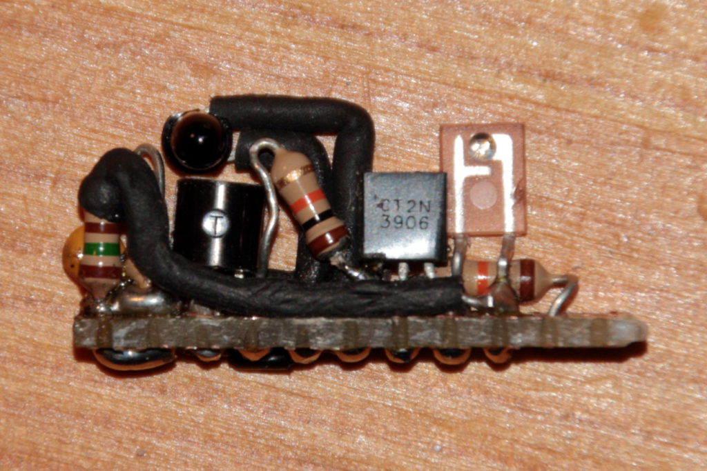
Not the tidiest bit of circuit, but works! However, in retrospect I might have fared better cutting a second strip, putting one on the top of the box, the other at the bottom. Might have made the alignment of the optical parts easier. If you have the possibility to etch a PCB, I’d recommend to go for this SMD version – is much nicer!
Finally, I cut a hole into the box for the cable, attached it to the circuit, crammed everything into the box and closed the box with tape at the edges. Then I attached the whole thing into the Optolink at the heating:
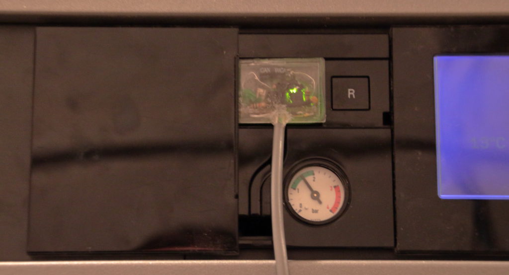
Works like a charm!
At the Raspberry, the pin assignments are:
| Circuit | Raspberry Pi Pin |
| 3.3 V | 1 |
| GND | 6 |
| TXD | 8 |
| RXD | 10 |
Setting up vcontrold on the Raspberry Pi
I was tempted to just refer to the openv wiki page, but since it is in German, I give the translated instructions here – as tested by me with Raspbian Stretch.
Prerequisites
You’ll need a few packages:
sudo apt-get install subversion automake autoconf telnet libxml2-dev
Set up Serial Port
Since Raspberry Pi 3 the serial port assignments changed a bit. The “real” UART is assigned/reserved for Bluetooth. However, we need it for the interface. Also, we do not want the linux console to clutter the interface.
/boot/config.txt should contain these two lines:
enable_uart=1
dtoverlay=pi3-miniuart-bt
and /boot/cmdline.txt should not contain console=serial0,115200 (or something similar). A reboot is required for this taking effect.
A more complete explanation can be found on this Raspberry foundation page.
Getting the Source Code, Compiling, Installation
This just takes a few minutes – no need to cross compile on a more powerful PC.
cd ~
mkdir openv
cd openv
svn checkout svn://svn.code.sf.net/p/vcontrold/code/trunk vcontrold-code
cd vcontrold-code/vcontrold
chmod +x auto-build.sh
./auto-build.sh
./configure
make
sudo make install
After that, in /usr/local/bin there should be vcontrold, vclient and vsim.
Create and Edit /etc/vcontrold.xml
First, create a config directory and copy the template config files from the source into it:
sudo mkdir /etc/vcontrold
sudo cp ~/openv/vcontrold-code/xml-32/xml/vito.xml /etc/vcontrold/
sudo cp ~/openv/vcontrold-code/xml-32/xml/vcontrold.xml /etc/vcontrold/
Modify the unix section of /etc/vcontrold.xml:
In section tty, change the interface to the Raspberry UART /dev/ttyAMA0.
In section net, add the IP ranges or addresses you’d like to access the data from.
Insert the device ID for your heating – the Vitovalor is 20E3. Other IDs you may find here (old Wiki page – will soon migrate). If your ID is not in the list and in case your heating also comes with access to the vitodata-server, go there to the heating, choose “Diagnostics”, open the device group and look for the ZE-ID. This is E3 for the Vitovalor, which means 20E3 as vcontrold ID.
<unix>
   <config>
      <serial>
         <tty>/dev/ttyAMA0</tty>
      </serial>
      <net>
         <port>3002</port>
         <allow ip='127.0.0.1'/>
         <allow ip='192.168.0.0/24'/>
      </net>
      <logging>
         <file>/tmp/vcontrold.log</file>
         <syslog>y</syslog>
         <debug>y</debug>
      </logging>
      <device ID="20E3"/>
   </config>
</unix>
Test
Try if the daemon comes up properly using vcontrold -n. This should open a telnet server on port 3002. Otherwise look into /tmp/vcontrold.log – this is often helpful for troubleshooting, also later when trying to figure out the commands.
Init-Script for vcontrold Autostart on Boot
Copy this script below to /etc/init.d/vcontrol – this is just copied from the opnev wiki page – all credits go there, or to be more precise to Michael Pucher (thanks a lot!). Then register the script:
cd /etc/init.d/
sudo chmod u+x vcontrol
sudo update-rc.d vcontrol start 99 2 3 4 5 . stop 99 0 1 6 .
And that’s it.
Using vcontrold
To access the heating via vcontrold, connect via telnet:
telnet localhost 3002
You’ll see a prompt. help will show you all available commands – in German… But the most interesting is the command commands – it shows all commands that you can send to the heating. Be aware that this is all at your own risk! As far as I understand, most of all is reverse engineered, and thus prone to errors that – worst case – might damage your heating! There is no official Viessmann support for the openv/vcontrold project.
Creating the Vitovalor-specific XML for vcontrold
The protocols implemented by the Viessmann heatings use address-value pairs. Some are read-only, others allow read/write operations. The vito.xml file contains the necessary definitions of addresses, values and units, along with the commands to get or set the values. The units vito.xml refers to are then defined in vcontrold.xml. While many addresses are the same across many Viessmann models, some are model-specific, or – worst case – have different meanings with different models.
Data Sources
It is not that easy to come by the addresses for a specific model. The following sources I used:
- The vito.xml files available in the openv pages (currently the old links, migration in progress):
- Coding lists from the manual and vitodata
- The datapoint lists for Vitogate 200 KNX – you must try to find someone at Viessmann who is willing to provide them. The page refers you to your local Viessmann sales agency, and indeed I got my list from them. Even if you do not use the Vitogate, the datapoint lists contain the right addresses.
- Educated guesses (there are some repeating patterns in the addresses which allow you to guess others) and trial-and-error
Totally not helpful was the Viessmann Community – the general idea is nice, but the people there are really reluctant to offer anything beyond simple information.
Educated Guessing of Addresses
There are some repeating patterns in the addresses with regard to the heat circuits/mixers. Often the first byte is indicating the heat circuit, the second the actual function. As an example:
0x2323 allows you to get/set the operation mode for heat circuit 1.
0x3323 does the same for heat circuit 2, and
0x4323 for heat circuit 3.
So, whenever you stumble across a working address 0x23??, it is worth to also try 0x33?? and 0x43??.
Here’s my list of “first bytes” I worked out for the three heat circuits:
| Heat circuit | First bytes |
| A1M1 or M1 | 0x20, 0x23, 0x25, 0x27, 0x29 |
| M2 | 0x30, 0x33, 0x35, 0x37, 0x39 |
| M3 | 0x40, 0x43, 0x45, 0x47, 0x49 |
Then, there are sometimes patterns in the second byte for heat circuits, and it seems to me that they are identical within the range of a first bye. An example:
0x0896, 0x0898 and 0x089A get the room temperatures for heat circuit 1, 2 and 3. And:
0x080A, 0x080C and 0x080E get the flow line temperatures for heat circuit 1, 2 and 3.
So I assumed (successfully) that within 0x08 any heat-circuit specific second byte may be used for the next heat circuit by adding an offset of 2 to it.
Here are the offsets I figured out (to be taken with a grain of salt – the statistics behind these assumptions are weak):
| First byte | Offset |
| 0x08 | 2 |
| 0x76 | 2 |
| 0xA4 | 64 (Hex: 40) |
Addresses Derived from Coding Lists
Both in the operation manual and in the vitodata server there are listings of the “Codings”. These give a single byte value in hex, so the aussmption is that these are part of an address. Matching a few addresses from existing vito.xml and the manual seem to confirm this. It looks like
- Codings that are not connected to a heat circuit go by address 0x77XX, where XX is the coding byte
- Codings that are assigned to heat circuits go by the addresses 0x27XX, 0x37XX and 0x47XX for heat circuit 1, 2 and 3, where again XX is the coding byte
I am currently testing this assumption, will update here as soon as I’m clear about it.
Completeness Check
The vitodata server shows zillions of parameters that the heating provides upon request. My guess is that all these parameters should be available via Optolink also. This said, I am far away from being complete, and most likely will never be.
For me, completeness will be achieved, if I can set all temperatures, set all operation modes, and read all temperatures, operation hours and power values. Especially the enrgy manager, which provides real-time data of my power consumption and production, I want to read out with high frequency.
When it comes to involved devices, in my case these components are in one way or another part of the data acquisition:
- Vitovalor 300-P (obviously)
- Vitotronic 200 RF (type HO1E)
- Vitocom 300 LAN3
- Saia PCD ALE3 M-BUS energy”manager” (Basically a two-way power meter)
All parts are the standard setup of the Vitovalor 300-P, i.e. if you get one, you should have the same setup.
Results
Below you’ll find my XML files – also vcontrold.xml needed adjustment for missing units. This is currently work in progress, and while this sentence is here, I am constantly improving the files. Again: Use these files at your own rsik! Currently I’d strongly recommend to only use the get commands, not the set commands, which may be totally wrong in some cases.
Known Issues
- Effective target temperatures currently yield nonsense results (unit conversion?)
- External room temperatures are unchecked because I don’t have external temperature sensors in my rooms
- Solar values are unchecked since I have no solar devices
- Modulation degree and relative device power are yet unchecked
- All set functions untested
Download Links
Last update: Nov. 19th, 2017
Appendix: Currently Implemented Functions
| Function | Description |
| getOpModeA1M1 | Get operation mode of the heat circuit 1. |
| setOpModeA1M1 | Set operation mode of the heat circuit 1. |
| getRequestedRoomTnormalA1M1 | Get normal room temperature target for heat circuit 1. (Range: 3..37°C) |
| setRequestedRoomTnormalA1M1 | Set normal room temperature target for heat circuit 1. (Range: 3..37°C) |
| getRequestedRoomTreducedA1M1 | Get reduced room temperature target for heat circuit 1. (Range: 3..37°C) |
| setRequestedRoomTreducedA1M1 | Set reduced room temperature target for heat circuit 1. (Range: 3..37°C) |
| getPartyModeA1M1 | Get party mode state for heat circuit 1 |
| setPartyModeA1M1 | Set party mode state for heat circuit 1 |
| getSavingsModeA1M1 | Get savings mode state for heat circuit 1 |
| setSavingsModeA1M1 | Set savings mode state for heat circuit 1 |
| getOpModeM2 | Get operation mode of the heat circuit 2. |
| setOpModeM2 | Set operation mode of the heat circuit 2. |
| getRequestedRoomTnormalM2 | Get normal room temperature target for heat circuit 2. (Range: 3..37°C) |
| setRequestedRoomTnormalM2 | Set normal room temperature target for heat circuit 2. (Range: 3..37°C) |
| getRequestedRoomTreducedM2 | Get reduced room temperature target for heat circuit 2. (Range: 3..37°C) |
| setRequestedRoomTreducedM2 | Set reduced room temperature target for heat circuit 2. (Range: 3..37°C) |
| getPartyModeM2 | Get party mode state for heat circuit 2 |
| setPartyModeM2 | Set party mode state for heat circuit 2 |
| getSavingsModeM2 | Get savings mode state for heat circuit 2 |
| setSavingsModeM2 | Set savings mode state for heat circuit 2 |
| getOpModeM3 | Get operation mode of the heat circuit 3. |
| setOpModeM3 | Set operation mode of the heat circuit 3. |
| getRequestedRoomTnormalM3 | Get normal room temperature target for heat circuit 3. (Range: 3..37°C) |
| setRequestedRoomTnormalM3 | Set normal room temperature target for heat circuit 3. (Range: 3..37°C) |
| getRequestedRoomTreducedM3 | Get reduced room temperature target for heat circuit 3. (Range: 3..37°C) |
| setRequestedRoomTreducedM3 | Set reduced room temperature target for heat circuit 3. (Range: 3..37°C) |
| getPartyModeM3 | Get party mode state for heat circuit 3 |
| setPartyModeM3 | Set party mode state for heat circuit 3 |
| getSavingsModeM3 | Get savings mode state for heat circuit 3 |
| setSavingsModeM3 | Set savings mode state for heat circuit 3 |
| getToutdoor_fcu | Get outdoor temperature [°C] (FCU data group) |
| getFCU_Hop | Get operation hours fuel cell unit |
| getRatioPconsumptionP_FCU | Get current ratio between electric power consumption and electric power of the FCU [%] |
| getRatioPproviderP_FCU | Get current ratio between electric power acquisition from service provider and electric power of the FCU [%] |
| getActiveBoilerTtarget | Get active boiler target temperature [°C] |
| getDeviceCurrentPrel | Get current device relative power production [%] |
| getBoilerFlowlineTcurrent | Get current boiler flowline temperatue [°C] |
| getWarmwaterTtarget_dhwc | Get effective warm-water target temperature [°C] (DHWC data group) |
| getAM1Output1 | Get AM1 output 1 |
| getAM1Output2 | Get AM1 output 2 |
| getEA1TargetValue | Get EA1 external target value 0-10V [0..120°C] |
| getEA1Contact0 | Get EA1 Contact 0 |
| getEA1Contact1 | Get EA1 Contact 1 |
| getEA1Contact2 | Get EA1 Contact 2 |
| getEA1Relay0 | Get EA1 relay 0 state |
| getCurrentOpModeHC1_hcc | Get current operation mode of heating ciurcuit 1 (HCC data group) |
| getEffectiveRoomTtargetHC1 | Get effective target room temperature for heat circuit 1 (0..35°C) |
| getCurrentOpModeHC2_hcc | Get current operation mode of heating ciurcuit 2 (HCC data group) |
| getEffectiveRoomTtargetHC2 | Get effective target room temperature for heat circuit 2 (0..35°C) |
| getCurrentOpModeHC3_hcc | Get current operation mode of heating ciurcuit 3 (HCC data group) |
| getEffectiveRoomTtargetHC3 | Get effective target room temperature for heat circuit 3 (0..35°C) |
| getExternalRoomTtargetNormalA1M1 | Get external normal target room temperature for heat circuit 1 (0..37°C – 0: the value set at the regulator is used) |
| setExternalRoomTtargetNormalA1M1 | Set external normal target room temperature for heat circuit 1 (0..37°C – 0: the value set at the regulator is used) |
| getHeatCircuitPumpA1 | Get heating pump state for heat circuit 1 |
| getFlowlineTtargetA1M1 | Get flowline target temperature for heat circuit 1 (0..127°C) |
| getExternalRoomTtargetNormalM2 | Get external normal target room temperature for heat circuit 2 (0..37°C – 0: the value set at the regulator is used) |
| setExternalRoomTtargetNormalM2 | Set external normal target room temperature for heat circuit 2 (0..37°C – 0: the value set at the regulator is used) |
| getHeatCircuitPumpM2 | Get heating pump state for heat circuit 2 |
| getFlowlineTtargetM2 | Get flowline target temperature for heat circuit 2 (0..127°C) |
| getCurveSteepnessM3 | Get heating curve steepness for heat circuit 3 |
| setCurveSteepnessM3 | Set heating curve steepness for heat circuit 3 |
| getCurveShiftM3 | Get heating curve parallel shift for heat circuit 3 |
| setCurveShiftM3 | Set heating curve parallel shift for heat circuit 3 |
| getExternalRoomTtargetNormalM3 | Get external normal target room temperature for heat circuit 3 (0..37°C – 0: the value set at the regulator is used) |
| setExternalRoomTtargetNormalM3 | Set external normal target room temperature for heat circuit 3 (0..37°C – 0: the value set at the regulator is used) |
| getHeatCircuitPumpM3_hc | Get heating pump state for heat circuit 3 (HC data group) |
| getFlowlineTtargetM3 | Get flowline target temperature for heat circuit 3 (0..127°C) |
| getCurveSteepnessA1 | Get heating curve steepness for heat circuit 1 |
| setCurveSteepnessA1 | Set heating curve steepness for heat circuit 1 |
| getCurveShiftA1 | Get heating curve parallel shift for heat circuit 1 |
| setCurveShiftA1 | Set heating curve parallel shift for heat circuit 1 |
| getCurrentOpModeA1M1 | Get current operation mode of heating ciurcuit 1 |
| getHeatCircuitPumpA1M1_hc | Get heating pump state for heat circuit 1 (HC data group) |
| getPartyModeA1M1_hc | Get party mode state for heat circuit 1 (HC data group) |
| getTroomA1M1 | Get room temperature of heat circuit 1 (0..127°C) |
| getSavingsModeA1M1_hc | Get savings mode state for heat circuit 1 (HC data group) |
| getTflowlineA1M1 | Get flowline temperature of heat circuit 1 (0..150°C) |
| getCurveSteepnessM2 | Get heating curve steepness for heat circuit 2 |
| setCurveSteepnessM2 | Set heating curve steepness for heat circuit 2 |
| getCurveShiftM2 | Get heating curve parallel shift for heat circuit 2 |
| setCurveShiftM2 | Set heating curve parallel shift for heat circuit 2 |
| getCurrentOpModeM2 | Get current operation mode of heating ciurcuit 2 |
| getHeatCircuitPumpM2_hc | Get heating pump state for heat circuit 2 (HC data group) |
| getPartyModeM2_hc | Get party mode state for heat circuit 2 (HC data group) |
| getTroomM2 | Get room temperature of heat circuit 2 (0..127°C) |
| getSavingsModeM2_hc | Get savings mode state for heat circuit 2 (HC data group) |
| getTflowlineM2 | Get flowline temperature of heat circuit 2 (0..127°C) |
| getCurrentOpModeM3 | Get current operation mode of heating ciurcuit 2 |
| getPartyModeM3_hc | Get party mode state for heat circuit 3 (HC data group) |
| getTroomM3 | Get room temperature of heat circuit 3 (0..127°C) |
| getSavingsModeM3_hc | Get savings mode state for heat circuit 3 (HC data group) |
| getTflowlineM3 | Get flowline temperature of heat circuit 3 (0..127°C) |
| getTexhaust | Get exhaust temperature (0..500°C) |
| getLowpassedToutdoor | Get outdoor temperature subject to lowpass filter with 30 minutes time base [°C] |
| getBurnerHop | Get operation hours of burner |
| setBurnerHop | Set operation hours of burner |
| getBurnerStarts | Get number of burner starts |
| setBurnerStarts | Set number of burner starts |
| getBoilerInput | Get boiler input 0-10V [°C] |
| getInternalPump | Get internal pump state |
| getBoilerTtarget | Get boiler target temperature [°C] |
| getBoilerTcurrent | Get current boiler temperature (0..127°C) |
| getModulationDegree | Get degree of modulation [%] |
| getInternalExtensionRelayK12 | Get K12 internal extension relay state |
| getCollectiveError | Get collective error condition |
| getRelayHeatCircuitPump1 | Get relay state for heating pump of heat circuit 1 |
| getSolarHop | Get operation hours of solar panels |
| getSolarTcollector | Get temperature of solar collector (-20..250°C) |
| getSolarPump | Get solar pump state |
| getSolarTstorage | Get solar storage temperature (0..127°C) |
| getSolarPheat | Get total solar power harvest [kWh] |
| getSolarPtoday | Get solar power harvest today [kWh] |
| getWarmwaterTout | Get warm-water outflow temperature (0..150°C) |
| getBufferTtop | Get buffer temperature top [°C] |
| getBufferTbottom | Get buffer temperature bottom [°C] |
| getBufferLoadingPump | Get buffer loading pump state |
| getBufferTcomfort | Get buffer loading sensor/comfort sensor temperature (0..150°C) |
| getWarmwaterTtarget | Get warm-water target temperature (10..60°C) |
| setWarmwaterTtarget | Set warm-water target temperature (10..60°C) |
| getWarmwaterCirculationPump | Get warm-water circulation pump state |
| getPartyTtargetA1M1 | Get target temperature in party mode state |
| setPartyTtargetA1M1 | Set target temperature in party mode state |
| getOpModeHoliday | Get holiday operation mode state |
| getLeavingDate | Get first day of holidays |
| setLeavingDate | Set first day of holidays |
| getArrivalDate | Get last day of holidays |
| setArrivalDate | Set last day of holidays |
| getToutdoor_vito | Get outdoor temperature (Vito data group) |
| getWarmwaterTcurrent | Get current warm-water temperature |
| getFlameState | Get current flame status |
| getTreturnFlow | Get return flow temperature |
| getWarmwaterHeatingValveState | Get state of valve switching between heating and warm-water |
| getTimerMonM1 | Get heat circuit 1 switching times for Monday |
| setTimerMonM1 | Set heat circuit 1 switching times for Monday |
| getTimerTueM1 | Get heat circuit 1 switching times for Tuesday |
| setTimerTueM1 | Set heat circuit 1 switching times for Tuesday |
| getTimerWedM1 | Get heat circuit 1 switching times for Wednesday |
| setTimerWedM1 | Set heat circuit 1 switching times for Wednesday |
| getTimerThuM1 | Get heat circuit 1 switching times for Thursday |
| setTimerThuM1 | Set heat circuit 1 switching times for Thursday |
| getTimerFriM1 | Get heat circuit 1 switching times for Friday |
| setTimerFriM1 | Set heat circuit 1 switching times for Friday |
| getTimerSatM1 | Get heat circuit 1 switching times for Saturday |
| setTimerSatM1 | Set heat circuit 1 switching times for Saturday |
| getTimerSunM1 | Get heat circuit 1 switching times for Sunday |
| setTimerSunM1 | Set heat circuit 1 switching times for Sunday |
| getTimerMonWW | Get warm-water switching times for Monday |
| setTimerMonWW | Set warm-water switching times for Monday |
| getTimerTueWW | Get warm-water switching times for Tuesday |
| setTimerTueWW | Set warm-water switching times for Tuesday |
| getTimerWedWW | Get warm-water switching times for Wednesday |
| setTimerWedWW | Set warm-water switching times for Wednesday |
| getTimerThuWW | Get warm-water switching times for Thursday |
| setTimerThuWW | Set warm-water switching times for Thursday |
| getTimerFriWW | Get warm-water switching times for Friday |
| setTimerFriWW | Set warm-water switching times for Friday |
| getTimerSatWW | Get warm-water switching times for Saturday |
| setTimerSatWW | Set warm-water switching times for Saturday |
| getTimerSunWW | Get warm-water switching times for Sunday |
| setTimerSunWW | Set warm-water switching times for Sunday |
| getTimerMonWWcirculation | Get warm-water circulation pump switching times for Monday |
| setTimerMonWWcirculation | Set warm-water circulation pump switching times for Monday |
| getTimerTueWWcirculation | Get warm-water circulation pump switching times for Tuesday |
| setTimerTueWWcirculation | Set warm-water circulation pump switching times for Tuesday |
| getTimerWedWWcirculation | Get warm-water circulation pump switching times for Wednesday |
| setTimerWedWWcirculation | Set warm-water circulation pump switching times for Wednesday |
| getTimerThuWWcirculation | Get warm-water circulation pump switching times for Thursday |
| setTimerThuWWcirculation | Set warm-water circulation pump switching times for Thursday |
| getTimerFriWWcirculation | Get warm-water circulation pump switching times for Friday |
| setTimerFriWWcirculation | Set warm-water circulation pump switching times for Friday |
| getTimerSatWWcirculation | Get warm-water circulation pump switching times for Saturday |
| setTimerSatWWcirculation | Set warm-water circulation pump switching times for Saturday |
| getTimerSunWWcirculation | Get warm-water circulation pump switching times for Sunday |
| setTimerSunWWcirculation | Set warm-water circulation pump switching times for Sunday |
| getError1 | Get error message 1 |
| getError2 | Get error message 2 |
| getError3 | Get error message 3 |
| getError4 | Get error message 4 |
| getError5 | Get error message 5 |
| getError6 | Get error message 6 |
| getError7 | Get error message 7 |
| getError8 | Get error message 8 |
| getError9 | Get error message 9 |
| getError10 | Get error message 10 |
| getSystemTime | Get current system time |
| getDeviceConfig | Get device configuration in use |
| getPartyTtargetM2 | Get target temperature in party mode state |
| setPartyTtargetM2 | Set target temperature in party mode state |
| getPartyTtargetM3 | Get target temperature in party mode state |
| setPartyTtargetM3 | Set target temperature in party mode state |
| getTimerMonM2 | Get heat circuit 2 switching times for Monday |
| setTimerMonM2 | Set heat circuit 2 switching times for Monday |
| getTimerTueM2 | Get heat circuit 2 switching times for Tuesday |
| setTimerTueM2 | Set heat circuit 2 switching times for Tuesday |
| getTimerWedM2 | Get heat circuit 2 switching times for Wednesday |
| setTimerWedM2 | Set heat circuit 2 switching times for Wednesday |
| getTimerThuM2 | Get heat circuit 2 switching times for Thursday |
| setTimerThuM2 | Set heat circuit 2 switching times for Thursday |
| getTimerFriM2 | Get heat circuit 2 switching times for Friday |
| setTimerFriM2 | Set heat circuit 2 switching times for Friday |
| getTimerSatM2 | Get heat circuit 2 switching times for Saturday |
| setTimerSatM2 | Set heat circuit 2 switching times for Saturday |
| getTimerSunM2 | Get heat circuit 2 switching times for Sunday |
| setTimerSunM2 | Set heat circuit 2 switching times for Sunday |
| getTimerMonM3 | Get heat circuit 3 switching times for Monday |
| setTimerMonM3 | Set heat circuit 3 switching times for Monday |
| getTimerTueM3 | Get heat circuit 3 switching times for Tuesday |
| setTimerTueM3 | Set heat circuit 3 switching times for Tuesday |
| getTimerWedM3 | Get heat circuit 3 switching times for Wednesday |
| setTimerWedM3 | Set heat circuit 3 switching times for Wednesday |
| getTimerThuM3 | Get heat circuit 3 switching times for Thursday |
| setTimerThuM3 | Set heat circuit 3 switching times for Thursday |
| getTimerFriM3 | Get heat circuit 3 switching times for Friday |
| setTimerFriM3 | Set heat circuit 3 switching times for Friday |
| getTimerSatM3 | Get heat circuit 3 switching times for Saturday |
| setTimerSatM3 | Set heat circuit 3 switching times for Saturday |
| getTimerSunM3 | Get heat circuit 3 switching times for Sunday |
| setTimerSunM3 | Set heat circuit 3 switching times for Sunday |
| getBoilerTcurrent_vito | Get current boiler temperature [°C] (Vito data group) |
| getFlowlineTcurrentM1 | Get current flowline temperature heat circuit 1 [°C] |
| getFlowlineTcurrentM2 | Get current flowline temperature heat circuit 2 [°C] |
| getFlowlineTcurrentM3 | Get current flowline temperature heat circuit 2 [°C] |
| getSolarWWstatus | Get solar load suppression status |
| getOpModeM1_vito | Get operations mode heat circuit 1 |
| setOpModeM1_vito | Set operations mode heat circuit 1 |
| getOpModeM2_vito | Get operations mode heat circuit 2 |
| setOpModeM2_vito | Set operations mode heat circuit 2 |
| getOpModeM3_vito | Get operations mode heat circuit 3 |
| setOpModeM3_vito | Set operations mode heat circuit 3 |
| getBurnerLevel2Hop | Get operation hours of burner level 2 |
| getDeviceType | Get device ID and type |
| getControllerID | Get ID of controller |
| getLowpassedBufferT | Get buffer temperature with lowpass applied [°C] |
| getInventory | Get number of device |
| getExternalRequest | Get status of external request |
| getExternalLock | Get status of external lock |
| getVolumetricFlow | Get volumetric flow of heat circuit [l/h] |
| getCodePlugInventory | Get number from code plug |
| getBufferPriorityA1M1 | Get buffer priority heat circuit 1 |
| setBufferPriorityA1M1 | Set buffer priority heat circuit 1 |
| getFrostLimitA1M1 | Get temperature limit for frost detection heat circuit 1 [°C] (KA3) |
| getSummerLogicA1M1 | Get summer mode logic function heat circuit 1 (KA5) |
| setSummerLogicA1M1 | Set summer mode logic function heat circuit 1 (KA5) |
| getAbsoluteSummerA1M1 | Get temperature limit for absolute summer savings mode heat circuit 1 [°C] (KA6) |
| setAbsoluteSummerA1M1 | Set temperature limit for absolute summer savings mode heat circuit 1 [°C] (KA6) |
| getBufferPriorityM2 | Get buffer priority heat circuit 2 |
| setBufferPriorityM2 | Set buffer priority heat circuit 2 |
| getFrostLimitM2 | Get temperature limit for frost detection heat circuit 2 [°C] (KA3) |
| getSummerLogicM2 | Get summer mode logic function heat circuit 2 (KA5) |
| getAbsoluteSummerM2 | Get temperature limit for absolute summer savings mode heat circuit 2 [°C] (KA6) |
| setAbsoluteSummerM2 | Set temperature limit for absolute summer savings mode heat circuit 2 [°C] (KA6) |
| getMixerInfluenceOnInternalPump | Get influence of the mixer on the internal circulation pump |
| setMixerInfluenceOnInternalPump | Set influence of the mixer on the internal circulation pump |
| getBufferPriorityM3 | Get buffer priority heat circuit 3 |
| setBufferPriorityM3 | Set buffer priority heat circuit 3 |
| getFrostLimitM3 | Get temperature limit for frost detection heat circuit 3 [°C] (KA3) |
| getSummerLogicM3 | Get summer mode logic function heat circuit 3 (KA5) |
| setSummerLogicM3 | Set summer mode logic function heat circuit 3 (KA5) |
| getAbsoluteSummerM3 | Get temperature limit for absolute summer savings mode heat circuit 3 [°C] (KA6) |
| setAbsoluteSummerM3 | Set temperature limit for absolute summer savings mode heat circuit 3 [°C] (KA6) |
| getLowpassedToutdoor_vito300 | Get outdoor temperature with lowpass applied (Vito300 data group) |
| getBurnerStatus | Get burner status |
| getBoilerToffsetToWW | Get boiler temperature offset related to warm-water temperature [°C] |
| setBoilerToffsetToWW | Set boiler temperature offset related to warm-water temperature [°C] |
| getCirculationPumpPostRun | Get status of warm-water circulation pump post run |
| setCirculationPumpPostRun | Set status of warm-water circulation pump post run |
| getPanelSoftwareIndex | Get index of panel software |
| getKScardType | Get type of KS card |
| getTflowlineM1_vito300 | Get current flowline temperature of heat circuit 1 [°C] (Vito300 data group) |
| getTflowlineM2_vito300 | Get current flowline temperature of heat circuit 2 [°C] (Vito300 data group) |
| getTflowlineM3_vito300 | Get current flowline temperature of heat circuit 3 [°C] (Vito300 data group) |
| getHeatCircuitPumpM3 | Get heating pump state for heat circuit 3 |
to be continued