since I play around quite a bit with electronics and software, and once in a while something comes out that might be of interest for the rest of the world, I decided to start this blog.
You may find here things about Raspberry Pi projects, Media centers, Home automation, Microcontrollers, Photography and a little programming, mainly in Python.
The blog will be updated on no particular schedule – whenever I think there’s something to share, you’ll find it here, but don’t be surprised if there is silence for several months.
To create a lamp with adjustable color temperature and brightness, I use a warm/cold white dual LED strip, an ATtiny45 MCU with N-channel MOSFETs and two adjustable resistors. This article contains the hardware and software setup. The title image of this blog shows the project.
To start with blogging projects, I picked the project shown in the title image. It certainly is not a very innovative project – you’ll find similar stuff all over the internet – but, well, I need some practice with the blog and all, so why not start simple?
So let’s start with the electronics for my
Color-adjustable, dimmable LED ceiling lamp
My girlfriend and I cannot find a nice ceiling lamp for our sofa niche, so we decided to build our own. It will be made from wood, shaped like a turned up boat, and the inner side will be plated with gold leaf. It’s not ready yet, so I can’t show any pictures. What we did so far is buying two boards of plywood, just 2 mm thick, and bent them using hot steam. That actually went very well already on the first try – we fixed the boards in the desired shape, heated water in two big pots and put the wood into the hot steam. We covered it with plastic shopping bags, and after 20-30 minutes of steaming the wood kept the desired form. Nice!
The goal
Since the lamp is supposed to light a place that should be cosy, but may also need bright, clear light at times, I decided that I want a lamp where I can adjust color temperature between warm white and cold white, as well as adjust the general brightness.
First approach: RGB LEDs → failure!
At first, I thought I go for RGB LED strips (aka. “Neopixels”), but this turned out to be stupid: You cannot get decent white light from these. The red, green and blue colors are far too narrow banded, not really covering the whole spectrum. If you look on e.g. a printed book cover (which uses CYMK-colors), the colors may look very strange in RGB LED “white” light.
Side remark: Now I have lying around a Neopixel LED strip – which brought me to the idea for another project, but this will be the topic of later posts.
Second approach: Dedicated cold/warm LEDs → much better.
So I bought this LED strip set. It has 150 cm of dual LED strip: There are warm white and cold white LEDs in it. Since these use some flourescent stuff to create white light from a blue or ultraviolet LED, they are broad spectrum and thus create nice light.
Part of the LED strip – LEDs offPart of the LED strip – LEDs on
The set comes with a controller and an IR remote that allows in principle exactly what I want: Adjust the color temperature, and dim the lamp. But…
I do not like having another remote lying around.
I do not think that my sofa niche lamp should need a battery (that of the remote).
The implementation is crappy: The adjustment steps are coarse (only eight brightness steps).
The priority is on equi-brightness – when I sweep from warm white to cold white, the general brightness keeps the same. The reasoning behind it is clear and sound, but as a result, the LED strip is powered at a maximum of 50%. So I do not get the full possible brightness.
Solution: Build my own LED controller
General design
I use the warm/cold dual LED strip from the purchased set, also the power supply (which is capable of driving up to 300 cm of the same strip, so if I drive all LEDs of 150 cm at full power, I’m well within specification), but create my own LED controller. This is…
using variable resistors to adjust brightness and color.
based on an ATtiny45 microcontroller (MCU). This is cheap, has builtin AD converters, and has two hardware PWM outputs.
Includes power supply (capable of driving 300 cm of LED strip), 150 mm of cold/warm dual LED strip (brightness equivalent to roughly a 70-100 W incandecent bulb), the (not-used) controller and IR remote. It is likely that with looking a bit around you’ll find this cheaper. And you might even use the controller box: It basically contains the MOS FETs, a voltage controller and a microcontroller (cannot tell which). If you do a little reverse engineering, you may just get away with the ATtiny45 and two variable resitors – or even use the remote and do a good implementation.
For 2.50 € I get an adjustable DC/DC buck converter with about 90% efficency – I did not even bother to think if I could build a different power source for the ATtiny.
1
Stripboard
1.- €
I wanted it to be long and narrow (10 × 40 wholes).
Mounting material
10.- €
Some clamps for the cable, screws, housing
#
Part
Source*
Price each (ca.)
Remarks
*Please note: I do not get any money from the distributors I mention here! The only reason I state the source is to help readers to acquire the parts if they have difficulty finding them. Most of the parts are available from plenty of distributors, and the ones I picked are usually not even the cheapest, but the most convenient for me. Especially Conrad has a store nearby, which is why I buy many parts there, despite the comparatively high prices.
If I do not state a source, I had the item lying around. You’ll get these things usually from any electronics distributor.
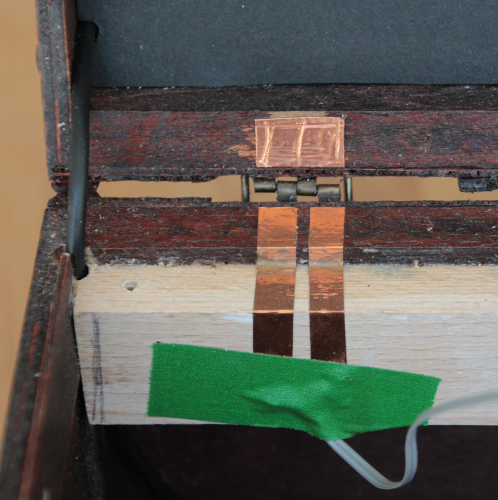
The circuit
The DC/DC converter takes the 24V from the power supply and provides 5V for the ATtiny. Be sure to adjust it to 5V before attaching the MCU.
The variable resistors are connected between 0V and 5V, so that the center pin will provide any voltage between these, dependent on knob position. I use linear resistors – any non-linear behaviour might in the end also be done by software. The center pin of the variable resistor is connected to one of the ADCs of the microcontroller, so that the knob position can be measured.
The brightness of the LEDs is controlled by pulse-width modulation (PWM). The ATtiny45 offers two hardware PWM outputs, which is really nice, since it takes away the need to implement software PWM, which always is tricky due to the tight timing requirements. It is capable of 8 bit PWM, so I have 256 bightness steps available for each warm and cold color LEDs. Setting the chip to 16 MHz speed, the PWM is of about 1 kHz, which means the light will not flicker.
The chip itself cannot stand the required voltage and current necessary to drive the LEDs, which is where the N-channel MOS FET comes into play. It can switch the 24V current on and off quickly enough to translate the 5V low power PWM of the ATtiny into high power pulses. These are fed into the LED strip, and the LEDs will appear brighter or dimmer, based on the duty cycle of the PWM.
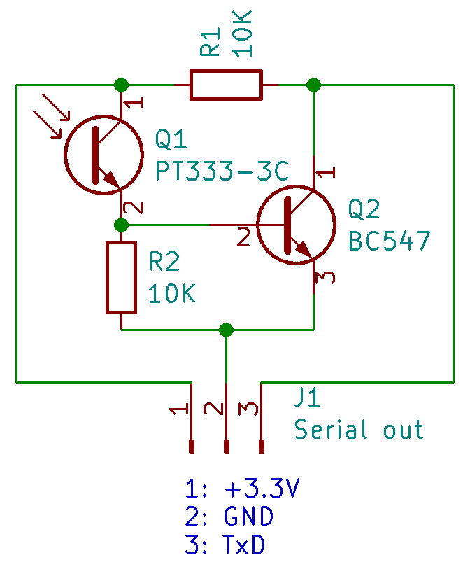
Here’s the circuit diagram (click for larger view):
The LED controller circuit
The software
The ATtiny can be programmed very well with the Arduino IDE. You need to import a board library – I use this one by David A. Mellis. My source code features…
reading the variable resitors and averaging (median) 17 measurements in order to minimize flicker from jumping least significant bit.
soft start feature: When switched on, the lamp will increase brightness “slowly” (i.e. within 1-2 sec) from 0 to the currently set brightness.
calculating the PWM values for the cold and warm LEDs. I do not aim for keeping brightness constant when changing color temperature. My algorithm is:
Get maximum brightness from variable resitor 1
Get color temperature fom variable resistor 2
for color resistor set between 0..50%, set…
warm LED to maximum brightness
cold LED linearly between 0..100% of maximum brightness
for color resistor set between 50..100%, set…
warm LED linearly between 100..0% of maximum brightness
cold LED to maximum brightness
The color temperature algorithm explained
As a result, at 50% color setting and 100% brightness setting, both LED colors are at full brightness, allowing me to get as much light as possible from the strip.
Source code
Please note: Set the fuses so that the microcontroller runs at least at 8 MHz, better even 16 MHz (PLL oscillator). This is to avoid any flicker from PWM. The internal oscillator of the ATtiny is sufficient, no need for an external one.
If you think 17 averaging values are wrong, adjust the line
#define AveragingReadouts 17
to meet your preference.
Source code is free for anyone to use and modify.
#include <stdlib.h>
#include <avr/pgmspace.h>

#define WarmLEDPin 0
#define ColdLEDPin 1
#define BrightnessPotPin A2
#define ColorPotPin A3
#define AveragingReadouts 17

unsigned int BrightnessReadout[AveragingReadouts];
unsigned int ColorReadout[AveragingReadouts];
unsigned int BrightnessCopy[AveragingReadouts];
unsigned int ColorCopy[AveragingReadouts];
long Brightness = 0;
long CurrentColor = 0;
long LastBrightness = 0;
long LastColor = 0;
long WarmPart;
long ColdPart;
long WarmCalc;
long ColdCalc;
uint8_t MedianIndex;
uint8_t ReadoutPointer = 0;
uint8_t ReadoutCounter;
boolean SoftOnDone = false;


void setup() {
  // put your setup code here, to run once:

  noInterrupts();
  pinMode(WarmLEDPin, OUTPUT);
  pinMode(ColdLEDPin, OUTPUT);
  pinMode(BrightnessPotPin, INPUT);
  pinMode(ColorPotPin, INPUT);
  analogWrite(WarmLEDPin, 0);
  analogWrite(ColdLEDPin, 0);
  MedianIndex = AveragingReadouts / 2;

}

void loop() {
  // put your main code here, to run repeatedly:

  BrightnessReadout[ReadoutPointer] = analogRead(BrightnessPotPin);
  ColorReadout[ReadoutPointer] = analogRead(ColorPotPin);
  ReadoutPointer++;
  if (ReadoutPointer == AveragingReadouts) {
    ReadoutPointer = 0;
  }

  // get median by sorting array and getting middle element
  for (ReadoutCounter = 0; ReadoutCounter < AveragingReadouts; ReadoutCounter++) {
    BrightnessCopy[ReadoutCounter] = BrightnessReadout[ReadoutCounter];
    ColorCopy[ReadoutCounter] = ColorReadout[ReadoutCounter];
  }
  sort (BrightnessCopy, AveragingReadouts);
  sort (ColorCopy, AveragingReadouts);

  CurrentColor = ColorCopy[MedianIndex];

  if (SoftOnDone) {
    Brightness = BrightnessCopy[MedianIndex];
  } else {
    delay (10);
    Brightness++;
    SoftOnDone = (Brightness >= BrightnessReadout[0]);
  }

  if ((Brightness != LastBrightness) || (LastColor != CurrentColor)) {
    LastBrightness = Brightness;
    LastColor = CurrentColor;

    WarmPart = min(CurrentColor, 511);               // 0..1023 --> 0..511..511
    ColdPart = 511 - max((CurrentColor - 512), 0);   // 0..1023 --> 511..511..0

    WarmPart *= Brightness;
    ColdPart *= Brightness;

    WarmCalc = min(WarmPart / 2050, 255);           // 2050 = 1023 * 511 / 255
    ColdCalc = min(ColdPart / 2050, 255);

    analogWrite(WarmLEDPin, byte(WarmCalc));
    analogWrite(ColdLEDPin, byte(ColdCalc));
  }

}

void sort(int a[], int size) {
    for(int i=0; i<(size-1); i++) {
        for(int o=0; o<(size-(i+1)); o++) {
                if(a[o] > a[o+1]) {
                    int t = a[o];
                    a[o] = a[o+1];
                    a[o+1] = t;
                }
        }
    }
}
The sort algorithm I have “stolen” from this page – thanks a lot Steve for sharing this!
Final remarks
To build all this yourself, you of course need a programmer for the ATtiny microcontroller. There are zillions around for less then 30.- €. I personally use this very simple parallel port programmer (sorry, link is German). This came at practically no cost since I had all parts lying around from old electronics. If you have to buy them, you’ll end up at about 10.- € – not worth the trouble: Buy a modern USB programmer instead. It will save you the need to find a computer with parallel port. Be aware that even that might not be sufficient – Windows 10 introduces a new driver scheme that spoils many software trying to access the parallel port directly.
There are two pins still unused on the ATtiny – you may even implement a switch that changes to equi-brightness mode or something…
As stated above, I built this on stripboard, which is my favorite “platform”. I currently lack the tools to etch my own PCBs, but I fare quite well without.
The circuit diagram was done using KiCad – thanks a lot to the community for this nice piece of software!
The BNO055 is a capable IMU that has on-chip sensor fusion and filtering. Interfacing can be done using I²C and UART. When used with the Raspberry via I²C, you get erroneous measurements because of the I²C clock stretching bug of the Raspberry. Using the UART, results are correct.
To skip directly to the correct connection of the BNO055 Xplained Pro board, click here.
I need a motion sensor…
For my upcoming project (which is not a Quadcopter/Drone/Robot project!) I need to track motion, both rotational as well as linear motion, to a few mm/arcsecond precision, using a Raspberry Pi Zero. Looking around, you quickly stumble across the MPU 6050, for which you find cheap breakout boards all over the internet. Hooking up and reading out sensor measurements is a rather simple thing, had it up and running in less than an hour. This post series is a very good quick start guide, and there is at least one python library on github.
The omnipresent MPU 6050 breakout board
But…
The values you get are everything but stable. Browsing the internet you learn about gyroscope drift, short term and long term fluctuations, nervous accelerometers and finally you arrive at the topic of sensor fusion, covariant filters and Kalman filters. This is deep dive stuff! For the curious: Some explanations can be found here. There is an Arduino implementation of a Kalman filter for the MPU 6050 which is supposedly bringing up nice and stable results, but I’d decided upon Raspberry for several reasons, and I could find no implementation for the Raspberry, and did not want to spend time porting code.
Finally, I found out that InvenSense, the manufacturer of the MPU 6050, “provides” ready made code for sensor fusion and filtering, that can run on the MPU 6050 itself, dubbed Digital Motion Processor (DMP). Registering with InvenSense you can download libraries and code examples for using the DMP, but all for different IDEs, not for Raspberries. And: this is proprietary code that is not well documented. It seems that the DMP is a binary code object that is uploaded to the MPU 6050 on start. There is the i2cdevlib which found a way to access and use the DMP (as far as I understand from porting the InvenSense code examples and extracting the firmware blobs), but again, only for Arduino. Certainly it would be possible to port this to the Raspberry – however: not done in a minute.
And there was a last catch: Obviously everyone using IMUs is only (or at least mainly) concerned about roll/pitch/yaw angles – linear acceleration just was not covered in nearly any guide, post or howto on the net. But I will badly need also a suffciently precise and robust linear motion measurement!
Since I want to go on with my project and not with the basics and mathmatics of inertial measurement units (IMUs), I needed to move on.
…and found Bosch BNO055.
Having learned about the term “sensor fusion”, I looked around for affordable IMU sensors that do the sensor fusion and filtering on-chip. I found the BNO055 Xplained Pro board from Atmel. Nearly a factor 3-10 more expensive as compared to MPU 6050 (depends if you order directly from the far east, or as I prefer local dealers), but still what I find reasonable. And it saves me days of work, and work of a kind I am not really craving for, having my project in mind. Finally, it offers nine “degrees of freedom” (9DOF), while MPU 6050 is 6DOF (not that I really need the magnetometer…).
The BNO055 Xplained Pro board comes in a fancy box…
Just as a side remark, in the meantime I learned that the quadcopter/flight control community offers capable boards which from the white papers sound very useful and sophisticated – it seems that cc3d might do the trick at half the price. And perhaps I may still need to try this out – the BNO055 spits out the fused mesurements at about 100 Hz, which may turn out too slow for my project. cc3d claims about 500 Hz.
Interfacing with the Raspberry
For my Proof of Concept (PoC) with the BNO055 I used a Raspberry 3. Adafruit offers a comprehensive guide and a Python library that already covers nearly everything, no need to repeat this all here.
Setting up the Adafruit library
Just a few lines and you’re done:
git clone https://github.com/adafruit/Adafruit_Python_BNO055
cd Adafruit_Python_BNO055
sudo python setup.py install
Using I²C – works, but not OK!
The Xplained Pro board is by default set to I²C communication mode, so I started there.
Working out the connections to the Xplained Pro board is easy using Atmel’s datasheet. You only need to connect power and the I²C lines, but the Adafruit library also makes use of the reset pin, so I recommend to connect this also. Furthermore, you may connect the interrupt pin, and there is a RGB LED on board, where each color may be switched when connected to a Raspberry GPIO pin. However, interrupt and LED are not used by the library, so it’s mainly for future use.
Here’s what goes where:
I²C connections
Raspberry Pi
Xplained Pro
Remarks
Pin #
Function
Pin #
Function
1
3.3 V
20
VCC
3
SDA
11
SDA
5
SCL
12
SCL
7
GPIO 4
9
INT
optional – Interrupt may be configured to trigger e.g. on motion detection
9
GND
19
GND
11
GPIO 17
15
RESET
optional, recommended – Allows to reset the BNO055 chip via GPIO
13
GPIO 27
7
LED B
optional – The board has a RGB LED on it. Each color may be switched via GPIO. Low means the LED is on.
15
GPIO 22
8
LED R
16
GPIO 23
6
LED G
…and how it looks in real life (no LED wires…)
In order to read data, in the files from Adafruit in Adafruit_Python_BNO055 you’ll find a file examples/simpletest.py. At the beginning of the script the sensor connection is defined, starting with bno=…. This line needs the following modification:
bno = BNO055.BNO055(rst=17, address=0x29)
assuming that your reset pin is connected to GPIO 17. The I²C address 0x29 can be found in the BNO055 datasheet (and be modified using the ADDR0 pin), which can be found along with a lot of other documentation on the Bosch product page.
In addition, I am interested in the linear motion, so I added a few lines in the while True: loop at the end of the script to get these values also:
while True:
    # Read the Euler angles for heading, roll, pitch (all in degrees).
    heading, roll, pitch = bno.read_euler()
    # Read the linear acceleration
    x_acc, y_acc, z_acc = bno.read_linear_acceleration()
    # Read the calibration status, 0=uncalibrated and 3=fully calibrated.
    sys, gyro, accel, mag = bno.get_calibration_status()
    # Print everything out.
    print('Heading={0:0.2F} Roll={1:0.2F} Pitch={2:0.2F}\tx_acc={3:0.2F} y_acc={4:0.2F} z_acc={5:0.2F}\tSys_cal={6} Gyro_cal={7} Accel_cal={8} Mag_cal={9}'.format(
          heading, roll, pitch, x_acc, y_acc, z_acc, sys, gyro, accel, mag))
When you now start the code using
sudo python simpletest.py
the readings come in. Now you need to follow the calibration procedure as described in the Adafruit guide. With the Raspberry 3 it seems to work very nice. But it only seems so! Looking a little bit closer, you’ll notice some oddities. Here are some example readings that show this:
Looks totally sane – the only thing: The chip is completely at rest, lying on the table, no movement. But still acceleration in x direction? This comes only at certain positions, not everywhere.
And finally, once in a while a line like this turns up:
In the end it turned out that I did not read the Adafruit guide carefully enough. The Raspberry has a problem with I²C clock stretching, which is actually a hardware bug. Look for “clock stretching” in the Adafruit guide, it’s explained there and you’ll find additional links. Actually, had I used an older Raspberry version, most likely the chip would not have worked at all.
Fortunately, the chip can also be interfaced…
Using UART – OK!
The BNO055 datasheet states that the PS0 and PS1 pins allow the selection of the protocol:
PS0
PS1
Protocol
0
0
I²C
1
0
HID via I²C
0
1
UART
1
1
Reserved
The PS0 and PS1 pins are availabe at the lower right of the Xplained Pro board (J103 in the Circuit diagram), along with 3.3 V, so just a wire bridge switches the chip to UART mode, and you connect it to the Raspberry UART instead of the I²C pins:
UART connections
Raspberry Pi
Xplained Pro
Remarks
Pin #
Function
Pin #
Function
1
3.3 V
20
VCC
7
GPIO 4
9
INT
optional – Interrupt may be configured to trigger e.g. on motion detection
8
TXD
12
RXD
UART
9
GND
19
GND
10
RXD
11
TXD
UART
11
GPIO 17
15
RESET
optional, recommended – Allows to reset the BNO055 chip via GPIO
13
GPIO 27
7
LED B
optional – The board has a RGB LED on it. Each color may be switched via GPIO. Low means the LED is on.
15
GPIO 22
8
LED R
16
GPIO 23
6
LED G
A few things need to be done on the Raspberry 3 using Jessie:
The Raspberry SVG image used above I’ve “stolen” from the Fritzing parts library, along with a few more parts. I think I’ll have a closer look on this software in the future – seems like a really nice program!
Only recently I stumbled across this comparison of sensor fusion implementations – worth a read if you’re currently chasing for your solution.
The Waveshare/Joy-IT 3.2″ touch display for Raspberry Pi is well suited for embedded applications that require a dynamic but small user interface. This article describes the steps required to get it working with Jessie, X and Python.
Preface
This is more for myself to document the steps necessary to connect and install my 3.2″ touch display to my Raspberry. Nothing new here you would not find somewhere else also.
The device
The 3.2″ touch display has a resolution of 320×200 pixels and comes with a small plastic touch pen. I got mine from Conrad, but you find this kind of display at several dealers. Distrubutor is Joy-IT, and they maintain software and documentation here. They again seem to redistribute a display from Waveshare. It seems that there are also badly made clones of it – you need to look closely. The display connects to the “old” 26-pin header of the Raspberry, but works also with the 40-pin versions.
The device uses SPI to interface with the TFT display.
The documentation you find is not always complete, so here is how to get this thing up and running on Jessie. Good thing: It works with the official Raspbian image, no need to get some badly maintained image from the manufacturer or compile anything yourself.
Installing the display
In principle, this guide is nearly complete. Here’s the synopsis:
Get the driver:
sudo bash
cd /boot/overlays
wget http://www.joy-it.net/anleitungen/rpi/tft32b/waveshare32b-overlay.dtb
mv waveshare32b-overlay.dtb waveshare32b.dtbo
The last line is important, since with Jessie the overlay names changed.
Add to /boot/config.txt:
dtparam=spi=on
dtoverlay=waveshare32b:rotate=270
Add to the single line in /boot/cmdline.txt:
fbcon=map:10
After reboot, some boot messages will still go to the default display, i.e. HDMI or composite video, but after a short while, you’ll see the console turning up on the display.
Setting up the X interface
To use the dispaly and the touch ability with the graphical desktop (which does not really make sense due to the tiny screen resolution), you need to edit (or create) /usr/share/X11/xorg.conf.d/99-calibration.conf:
After reboot, there should be /dev/input/touchscreen.
Touch as console mouse (not really…)
I could not find a way to make the touch screen work as a console mouse, but at least I could achieve that touching the display causes the screen to wake up from sleep/screen blanking. For this I installed gpm:
sudo apt-get install gpm
This on the first glance seems to work, but it does not: The cursor does not follow the pen, because gpm does interpret the output as relative movement. Changing /etc/gpm.conf to:
lets you test the screen – you may even draw on it
This step is optional if you do not rotate the display. As soon as the display is roteted, the calibration in /etc/pointerconf will automagically take care of this rotation in programs – at least if they use tslib, among them the pygame library for Python. No idea currently what other software uses /etc/pointerconf.
Adjusting the console to the tiny resolution
The standard font does not let you see very much on the tiny screen. Run
sudo dpkg-reconfigure console-setup
You’ll be guided through some menus. Pick
Charset: “UTF-8”
“Guess optimal character set”
Pick the font face – I reccommend “Terminus”
Pick the character size – I recommend “6×12”
You need a little patience, but then you’ll see the font change on the display.
Here’s the display in action on a Raspberry Pi Zero (please note: this is with “dtoverlay=waveshare32b:rotate=0” in /boot/config.txt):
The 3.2″ TFT display in action
GPIO availability
A drawback of the display is that it blocks the first 26 GPIO header pins. However, not all are used. According to the Conrad and Waveshare pages, this is the situation (GPIO assignment given for Rev 1 Pi):
Pin #
Raspberry function
Display function
Pin #
Raspberry function
Display function
1
3.3 V
3.3 V
2
5 V
5 V
3
GPIO 2/I²C SDA
4
5 V
5V
5
GPIO 3/I²C SCL
6
GND
GND
7
GPIO 4
8
GPIO 14/UART TxD
9
GND
GND
10
GPIO 15/UART RxD
11
GPIO 17
TP_IRQ – Touch Panel interrupt, low while touch detected
12
GPIO 18/PWM
Button 0/Key 1
13
GPIO 27
RST – Reset
14
GND
GND
15
GPIO 22
DC – Instruction/Data Register selection
16
GPIO 23
Button 1/Key 2
17
3.3 V
3.3 V
18
GPIO 24
Button 2/Key 3
19
GPIO 10/SPI MOSI
MOSI
20
GND
GND
21
GPIO 9/SPI MISO
MISO
22
GPIO 25
23
GPIO 11/SPI SCK
SCK
24
GPIO 8/SPI CE0
CE0 – LCD chip selection, low active
25
GND
GND
26
GPIO 7/SPI CE1
CE1 – Touch Panel chip selection, low active
Good: I²C and UART are unused and free. Bad: PWM is used for one of the hardware keys. And: No backlight control. There are other, similar displays that offer backlight control – if it is important to you, go look around.
Using with Python
Prerequisites for Jessie (as of March 2017)
Using the touchscreen with Jessie, Python and the pygame library is surprisingly complicated to get to work – this forum post finally helped me to get it running. Unless you run the following steps, the touchscreen readings are simply nonsense! Cause is a compatibility issue with the touchscreen, SDL and Jessie.
Necessary steps:
Make the old Wheezy repository for the SDL library available to dpkg
Switch SDL library to have the Wheezy archive as default repository
Force downgrade to SDL 1.2
Here’s the way to go, copied 1:1 from above’s post by heine (line breaks are intentional!):
#enable wheezy package sources
echo "deb http://archive.raspbian.org/raspbian wheezy main
" > /etc/apt/sources.list.d/wheezy.list

#set stable as default package source (currently jessie)
echo "APT::Default-release \"stable\";
" > /etc/apt/apt.conf.d/10defaultRelease

#set the priority for libsdl from wheezy higher then the jessie package
echo "Package: libsdl1.2debian
Pin: release n=jessie
Pin-Priority: -10
Package: libsdl1.2debian
Pin: release n=wheezy
Pin-Priority: 900
" > /etc/apt/preferences.d/libsdl

#install
apt-get update
apt-get -y --force-yes install libsdl1.2debian/wheezy
Before you follow these steps: If you read this quite a while after March 2017 (when I wrote these lines), it may be worth a try without the downgrade. Maybe the bugfix is there by then.
Accessing the screen with pygame
Install pygame:
sudo apt-get install python-pygame
Run the steps above for linking and tslib, including calibration if the display is rotated.
And here’s some sample code, inspired by Jeremy’s Blog (recommended to read for more touchscreen/GUI inspirations):
import pygame, time, os, logging

# Set environment variables for correct use of touchscreen
os.putenv('SDL_VIDEODRIVER', 'fbcon')
os.putenv('SDL_FBDEV', '/dev/fb1')
os.putenv('SDL_MOUSEDRV', 'TSLIB')
os.putenv('SDL_MOUSEDEV', '/dev/input/touchscreen')

# Init logs
logging.basicConfig(filename='test.log',level=logging.DEBUG)

# Init the pygame library and the display
pygame.init()
pygame.display.init()
DisplaySize = (pygame.display.Info().current_w, pygame.display.Info().current_h)

# Log the detected display size
logging.info(DisplaySize)

# Open fullscreen window
MainDisplay = pygame.display.set_mode(DisplaySize, pygame.NOFRAME)

while True:
    # Wait for touchscreen touch events, until a keyboard key is pressed
    for event in pygame.event.get():
        if (event.type is pygame.MOUSEBUTTONDOWN):
            # Get touch position and write to log
            pos = pygame.mouse.get_pos()
            logging.info(pos)
        elif (event.type is pygame.MOUSEBUTTONUP):
            # Get finger lift position and write to log
            pos = pygame.mouse.get_pos()
            logging.info(pos)
	elif (event.type is pygame.KEYDOWN):
            # Key pressed --> End program
            quit()

    time.sleep(0.1)
The Raspberry Pi with Kodi is a versatile media center. Getting it to work with German IPTV in a stable fashion is however somewhat challenging. In this post I outline the necessary steps to set up a XBian based media center, to make it usable on a rather small SD TV screen, to avoid the 30 minutes offset problem with the public German TV stations, to make the channel mappings stable and to control the media center via IR remote control.
As usual, the article starts with lots of blah blah – you may skip this an directly read about
There are some dependencies in the text – maybe you’ll need to scroll back if you jump in late and want to understand everything.
Preface
Germany switched off DVB-T on March 27th 2017, replacing it with DVB-T2 – German style. I.e. HD with H.265/HEVC codec, and: the privatly owned TV stations encrypted. To watch them, you’d need to pay about 70,- € per year to “freenet”. Ridiculous! Why would I pay money to see commercial-infested linear TV? For about the same price that Netflix, Amazon Prime and the rest charge for commercial-free, self-directed TV? No way! And: DVB-T was introduced in Germany only about 10 years ago – and now millions of devices can be thrown away. Long story short: I decided to not longer support this nonsense ad looked how far I can get with a Media Center and IPTV live streams from the public TV stations.
My Raspberry Pi based Media Center
Choosing the media center
Hardware base
One thing was more or less clear from the beginning: I’d want to use a Raspberry Pi. Why? First: I already have it. Second: Low power consumption. Third: It’s cheap. Fourth: It’s currently well suited for the task, having MPEG-2 and H.264 hardware decoding on board. Fifth: If it at some point is no longer the right hardware, I have other use for it – unlike my now old DVB-T receiver, which I can perhaps use the power supply of, but else can only trash or harvest for parts.
Heard a lot positive about Windows 7 Media center, but having a full fledged PC in my living room just for TV? No…
However, there are disadvantages, but for the time being I can ignore them: H.265/HEVC is on the doorstep – it is only a question of time until the Raspberry Pi will not be the ideal device anymore, unless the Raspberry Foundation comes up with something new. And: It is not easy to put into standby for really low power consumption – but this may be altered using a real time clock. Will investigate this if the media center has survived the first two or three months and proven its usefulness.
Software
Having Raspberry Pi as hardware base, I could only find one kind of media center for it: Kodi. But this exsits in several flavours: As native Raspbian package, OpenELEC, LibreELEC, OSMC and XBian. Which is the best? I tried them all (except for the native package), and honestly: I could hardly find any difference. Not sure why they exist in parallel… In the end I settled for XBian for two reasons: First, it’s a rolling distribution, no need to at some point restart from scratch, and second: It had the newest tvheadend package built in – and as it turned out (details follow below) this was crucial to get IPTV running.
Setting up XBian
There are zillions of tutorials how to do that – a very exhaustive German blog post series is written by Helmut Krager (2015 – not everything written there is still completely true), but in principle the XBian getting started page is enough to get it up and running. On Unknown Blog you find explanations to get the SD card ready for Windows, MAC and Linux – if you struggle at that point, look at this page.
Challenge: My rather small SD TV set!
While things are rather boring up to here, challenges start at my TV set. It is an old CRT device with an effective screen diogonal of 36 cm – thats 14 inches. SD resolution of course. At this point you may realize that watching TV is not our favorite pastime
Connecting it
That’s the easy part: Since the Raspberry Pi shoots out composite video, and the CRT, old as it may be, still has a SCART connector, this works. I had lying around a SCART to RCA/Cinch adapter, and I bought a tip-ring-ring-sleeve jack to cinch adapter. Works like a charm – just be aware that these adapters come in different pin configurations. This page perfectly explains the details.
Configuring the Raspberry Pi
Besides the basic stuff like setting a hostname and changing the default password, the composite video signal needs setup for German PAL TV norm by modifying /boot/config.txt:
sdtv_mode=2
sdtv_aspect=1
This sets PAL and 4:3 aspect ratio. And thats it.
Finding an appropriate theme for Kodi
I tried them all. I think about 20 themes come along with XBian, all claiming to offer a sleek, versatile, clean UI. None is uasble at SD resolution on a small screen. You can’t read the text, unless you sit directly in front of the screen, and the fonts you may choose from don’t help. Fortunaltely, after quite an odyssey, I stumbled across someone who had the same problem and published the Confluence 480 theme as a modification of the original Confluence theme. And here is how you set it up (needs the command line/SSH as user xbian):
git clone https://github.com/YggdrasiI/skin.confluence.480.git
cd skin.confluence.480
python ./templates/config.py
python ./buildPackage.py
cd /dev/shm
mv ./skin.confluence.480 /home/xbian/.kodi/addons
If the first command fails, you may not have git toolset installed. Just do
sudo apt-get install git
Restart Kodi and select the theme as usual. I also changed the font to large font. Don’t forget to do the video calibration and adjust the theme zoom.
Now it’s well readable on my TV – yay!
…and here it is in all it’s beauty
Setting all up for German public IPTV
While getting XBian up and running is a piece of cake, getting German IPTV stations up and running in a stable fashion turned out to be quite difficult. I was rather surprised that nobody yet has done it and written about it somewhere.
Goal
Being used to some features from my old DVB-T receiver, I wanted to have:
Timeshift
Recording capabilities
Watch a TV station while another is recorded (had a twin tuner before)
Watch a still running recording
Use an IR remote control
Not good: IPTV simple client
99% of all howto’s on the net tell you: Watch IPTV with IPTV simple client. While it is true that this works very well, it does not offer any of my required features. Not happy…
From playing around with tvheadend (years ago when the first Raspberry Pi came out and I wanted to attach my DVB-T USB card to it), I knew that tvheadend – although not being very intuitive to set up – offers what I needed. So let’s…
Install tvheadend Server
I’m a friend of using built-in packages when offered – so to install tvheadend use XBian’s built-in setup tool that starts up when you log in via commandline/SSH:
Navigate to “Packages”Select “video”Activate tvheadend
Then choose “Install/Update” (Since I did already, it says “Yes” in the screenshot above):
Select Install/Update
tvheadend Client/Frontend
To use tvheadend in Kodi, you need to install the add-on “Tvheadend HTSP Client”. Just do it the standard way, and activate it. The default configuration should be OK.
This add-on already covers all my requirements from above by being a PVR add-on to Kodi. The Kodi built-in features for recording, timeshift etc. will work out of the box as soon as the TV channels are set up.
Setting up TV channels
German IPTV uses HTS streams. There is a good documentation how HTS works on the net from Apple. The basic procedure to use HTS in tvheadend is relatively simple, but has it’s pitfalls:
Open tvheadend web interface with any browser using http://<IP of your Raspberry Pi>:9981/
Go to Configuration – DVB Inputs – Networks
Find out the live stream m3u8 playlist of each TV station – e.g. here. Looks like something like this: http://daserste_live-lh.akamaihd.net/i/daserste_de@91204/master.m3u8
Choose the “+ Add” button
Add a new IPTV stream
Choose IPTV Automatic Network
Choose network tpye
Choose a name and paste the URL of the m3u8 playlist
Enter name and URL
Switch “View level” to “Expert” and change the EIT time offset to “Local (server) time” – only then your timed recordings will be correct. Be sure to also set Kodi/Raspberry/tvheadend to the correct timezone!
Set time zone for accurate recordings
Click “Create”.
What will happen now is that tvheadend will scan the playlist and detects the actual streams (most TV stations offer more than one stream: different resolutions, and sometimes only the audio track). For each stream a “Mux” will be created. Each Mux (i.e. stream) will then be checked if it actually delivers data. If so, a “Service” is created for each active stream. The result is shown in the networks overview:
The network overview showing Mux and Service count
Our example network has 12 Muxes, but only 10 deliver data and are now Services.
Unfortunately, things get a little bit cumbersome from here on – but I’ll show solutions later that avoid the complexity of the next steps. But just to be complete, here’s how it goes on in principle:
On the “Services” tab you’ll see all the services created:
The new services
You see that they are indistiguishable from each other. You can check which is what by clicking on the “Play” symbol to the left. After a few seconds, you should see the stream in a media player (if this is supported by your OS/Computer/setup). You’ll see that some are low resolution, and some are higher resolutions. Also some in my case did not work at all.
A perhaps faster way to identify your services is to download the original IPTV playlist into a text editor. It will look like this:
You’ll notice that each stream is defined by a line starting with #EXT-X-STREAM-INF:, and another line stating an URL. The first line also states a resolution. This is a mandatory field, so you’ll always find it in the regarding playlists. It makes it easy for you to identify the streams of the desired quality.
You may be tempted to always pick the largest resolution available, but keep in mind a few things:
Larger resolution requires more internet bandwidth
Larger resolution results in larger recording files
So choose wisely
Now go to the “Muxes” tab and open a Mux (use “Edit”):
Assign a name to the mux
Now you can compare the URL of the mux, which tvheadend picked from the playlist, to the downloaded playlist. For services that match your criteria, you change the Mux name to something that helps you to identify it on the services tab for the next step.
Map services to an actual TV channel. For this select one or more services and pick “Map selected services”:
Identify desired services and map them
As you see, the Mux naming now helps you to identify the services in question. Leave the next dialog at default values:
Service mapping dialog
After clicking “Map services” the service mapper kicks in and will show you the result:
The service mapper in action
You’ll sometimes have services that are “ignored” – that’s usually OK, since they don’t deliver valid data.
Rename your channel and optionally assign a channel number:
Edit channel data
The automatically generated station name is not very cool, so rename it. Assigning a channel number is a good idea, since Kodi can use these numbers. I found this to be more stable than using the channel sorting and numbering from Kodi itself.
The tvheadend HTS client/Kodi will now pick up the channels and you can watch them, record them etc.
I tried recording three channels at the same time and watched a fourth – was no problem at all!
This is not stable…
While this in principle works, I had several problems:
The problem of finding the right resolution as described above – works, but is tedious work
The service-to-channel-assignments vanished after a while – some were gone after a day, some after two or three. A few stayed forever. Which in turn meant that the tedious work would start from scratch…
The public German IPTV channels all offer 30 minutes timeshift in their online player. As a result, the stream playlist covers 30 minutes of material. The tvheadend HTS client always starts at the top of the playlist – so you lag behind live TV by 30 minutes!
Leaving it as this, the media center would be worthless for me. But I found a…
Stable Solution
Overview
I created PHP scripts that run on the Raspberry Pi on a web server which filter and shorten the m3u8 playlists. To avoid losing the service-channel associations, I stored the TV station playlists for the networks locally.
In detail
Setting up the web server (may not be necessary)
I overlooked that XBian already has Apache2 on board, so I installed lighttp as well. It should be possible to do the same thing with Apache – even the config should be similar. However, here’s my way:
Install lighttp and PHP:
sudo apt-get install lighttpd php5-cgi
Now configure the webserver – I chose to use port 8000 for my scripts, just not to interfere with standard port 80 for web services. You need to edit /etc/lighttpd/lighttpd.conf (same lines should work with Apache):
([…] means lines that are inbetween are unmodified)
Version 1 (recommended): Filter by resolution and shorten stream playlist
As defined in the HTS specification, the stream playlist (which tvheadend imports as a Mux) is a rolling playlist that contains a number of short (typically 10s) stream fragments, the sequences. While the stream runs, new sequences are appended to the playlist, while older drop out. A snapshot of such a playlist may look like this (shortened):
As said earlier, German public IPTV contains 180 10s-sequences, adding up to 30 minutes of streaming material. In order to have really live-TV, this playlist needs to be shortened. I currently keep only the last 6 sequences, i.e. one minute of material in my playlists, and this seems to work reasonably stable (but may need fine tuning).
The shortening is done by /var/www/html/m3u8shorten.php:
<?php

	/*
	This script takes a m3u8 playlist that contains a sequence of transport streams. It
	drops all sequence URLs but the last ones - how many can be configured via GET variable.
	It adjusts the starting sequence number accordingly.

	Input GET variables:
	Keep		Number of sequences to keep
	TargetURL	URL of the original playlist
	ServiceName	Name of the TV service - is added to the playlist as #EXT-X-MEDIA:NAME= (currently ignored by tvheadend)

	Written by Hauke April 2017
	*/

	// Set correct content type for playlist
	header('Content-Type: application/x-mpegURL');

	// Read GET variables
	$M3u8URL = $_GET['TargetURL'];
	$SequencesToKeep = $_GET['Keep'];
	$ServiceName = $_GET['ServiceName'];

	// Download original playlist
	$M3u8 = file_get_contents($M3u8URL);

	// Split playlist into individual lines
    $M3u8Lines = explode("\n", $M3u8);

	// Arrays that will contain the individual transport stream URLs and the m3u8 EXTINF information
	$EXTINFs = [];
	$URLs = [];

	// Count sequences processed
	$Sequences = 0;

	// Loop through all lines
	foreach($M3u8Lines as $line) {
		if (strtoupper(substr($line, 0, 8)) == "#EXTINF:") {
			// EXTINF found --> Add to array
			$EXTINFs[] = $line;
		} else if (strtoupper(substr($line, 0, 4)) == "HTTP") {
			// URL found --> Add to array and count sequences +1
			$URLs[] = $line;
			$Sequences++;
		} else if (strtoupper(substr($line, 0, 22)) == "#EXT-X-MEDIA-SEQUENCE:") {
			// Filter out current sequence start number - needs to be updated later
			$MediaSequenceStart = substr($line, 22);
		} else if (strlen(trim($line)) > 0) {
			// Each other non-empty line is just echoed (assume it's a header line)
			echo $line . "\n";
		}
	}

	echo "#EXT-X-MEDIA:NAME=" . $ServiceName . "\n";

	// Adjust the starting sequence number and send it out
	echo "#EXT-X-MEDIA-SEQUENCE:" . ($MediaSequenceStart + $Sequences - $SequencesToKeep) . "\n";

	// now send out the desired number of sequence URLs from the end of the list
	for ($SequenceCounter = $Sequences - $SequencesToKeep; $SequenceCounter < $Sequences; $SequenceCounter++) {
		echo $EXTINFs[$SequenceCounter] . "\n";
		echo $URLs[$SequenceCounter] . "\n";
	}

?>
Running the above playlist through this script using http://<IP of Raspberry>:8000/m3u8shorten.php?Keep=5&TargetURL=<URL of playlist> would shorten it:
Note the changed line #EXT-X-MEDIA-SEQUENCE:148754138.
Having this, I now need to change the original TV station playlist to contain links to the m3u8shorten.php script. As a bonus, I include a filter by resolution. I specify a minimum resolution, and only streams that provide larger images are kept in the playlist. This avoids the effort of finding the desired services later in the service-to-channel assignment.
<?php

	/*
	This script adds to each URL in a m3u8-playlist a redirect-URL to the PHP-script that
	shortens the transport stream playlist to a given number of sequences. Only streams that
	satisfy a given horizontal resolution limit (default: 850 pixel) are kept.

	Hand over the following GET variables:

	Keep		Number of sequences to keep in the rolling playlists --> Is forwarded to the shorten-script
	TargetURL	URL of the MUX playlist that contains the rolling playlists for the services
	ResLimit	Horizontal resolution limit to filter the streams by. Only streams providing larger x-resolution are kept.
				If not provided: Default = 850 pixel.
	ServiceName	Name of the TV service - currently of no use --> Is forwarded to the shorten-script

	Written by Hauke April 2017
	*/

	// Set correct content type for playlists
	header('Content-Type: application/x-mpegURL');

	// Get GET-Variables
	$SequencesToKeep = $_GET['Keep'];
	$M3u8URL = $_GET['TargetURL'];
	$ServiceName = $_GET['ServiceName'];
	$ResLimit = $_GET['ResLimit'];

	// Set default if no resolution limit was specified
	if ($ResLimit == "") {
		$ResLimit = 850;
	}

	// Download original M3U8
	$M3u8 = file_get_contents($M3u8URL);

    // Split playlist into individual lines
    $M3u8Lines = explode("\n", $M3u8);

	$ValidURL = False;

	// Loop through all lines
	foreach($M3u8Lines as $line) {
		if (strtoupper(substr($line, 0, 18)) == "#EXT-X-STREAM-INF:") {
			// Extract resolution
			$ResolutionTagPos = stripos($line, "RESOLUTION=");
			if ($ResolutionTagPos > 0) {
				$EndTagPos = strpos($line, ",", $ResolutionTagPos);
				if ($EndTagPos < $ResolutionTagPos) {
					$EndTagPos = strlen($line);
				}
				$Resolution = substr($line, $ResolutionTagPos + 11, $EndTagPos + 11 - $ResolutionTagPos);
				$XYresolution = explode("x", $Resolution);
				// Check if horizontal resolution exceeds limit
				$ValidURL = ($XYresolution[0] > $ResLimit);
			} else {
				$ValidURL = False;
			}
			// only keep URL if resolution limit is satisfied
			if ($ValidURL) {
				echo $line . "\n";
			}
		} else if (strtoupper(substr($line, 0, 4)) == "HTTP") {
			// Again check for satisfied resolution limit. Lines always come in pairs, so this simple mechanism works.
			if ($ValidURL) {
				// Redirect to php script that shortens the playlist to desired number of sequences
				echo "http://127.0.0.1:8000/m3u8shorten.php?ServiceName=" . $ServiceName . "&Keep=" . $SequencesToKeep . "&TargetURL=" . $line. "\n";
				// reset flag
				$ValidURL = False;
			}
		} else if (strlen(trim($line)) > 0) {
			// Each other non-empty line is just echoed (assume it's a header line)
			echo $line . "\n";
		}
	}

?>
So if I have this playlist from above again, coming from http://daserste_live-lh.akamaihd.net/i/daserste_de@91204/master.m3u8:
You can see that the number of URLs is reduced due to the resolution limit, and the individual URLs point to the shorten-script from above.
Basically, you could now use the example call above as the IPTV automated network URL – works!
Optional: Nice Mux Naming
Now comes a last, optional thing, adding some eye-candy. If you use the above call directly, all muxes will be named “m3u8makemux.php”. If you want them named like the TV sation, follow these steps.
First, modify /etc/lightppd/lighttpd.conf so that the mod_redirect is enabled and then create a redirect rule:
The point of this is, that tvheadend will pick the name of the mux from what comes after the last “/” of the URL. As a result, tvheadend will now display the name of the mux as the TV station used in the nice URL from above. In my case this looks like this:
Mux names using redirected URL
This makes service assignement easier. However, since the network name is also given on each page, this is not really needed.
Version 2: Filter by resolution and use pipe://…
A user named Torsten made me aware of the pipe://… mechanism (thank you very much again!). This involves ffmpeg, and I never considered it since I thought ffmpeg is too load heavy for the Raspberry. What Torsten pointed out is that ffmpeg can just copy a stream, without CPU intense transcoding. ffmpeg is clever enough on its own to handle the streams so that the 30 minutes of available material are skipped and the playback starts at the end of the stream, making TV live again. Basically, a mux URL needs to look like this:
The really nice thing is that you can specify the parameter -metadata service_name=ARD, and this is picked up by tvheadend. As a result, the services have correct names!
Tiny issue: XBian does not come with ffmpeg. However, there is a package named avconv, which is basically the same, down to the command line options being identical. To install avconv use
Only ffmpeg was replaced by avconv, all else is like above.
Now the script to redirect the streams and filter by resolution looks like this:
<?php

	/*
	This script transcodes each URL in a m3u8-playlist to use the pipe://-mechanism.  Only streams that
	satisfy a given horizontal resolution limit are kept.

	Hand over the following GET variables:

	TargetURL	URL of the MUX playlist that contains the rolling playlists for the services
	ResLimit	Horizontal resolution limit to filter the streams by. Only streams providing larger x-resolution are kept.
				If not provided: Default = 850 pixel.
	ServiceName	Name of the TV service - used in the avconv command

	Written by Hauke April 2017
	*/

	// Set correct content type for playlists
	header('Content-Type: application/x-mpegURL');

	// Get GET-Variables
	$M3u8URL = $_GET['TargetURL'];
	$ServiceName = $_GET['ServiceName'];
	$ResLimit = $_GET['ResLimit'];

	// Set default if no resolution limit was specified
	if ($ResLimit == "") {
		$ResLimit = 850;
	}

	// Download original M3U8
	$M3u8 = file_get_contents($M3u8URL);

	// Split playlist into individual lines
	$M3u8Lines = explode("\n", $M3u8);

	$ValidURL = False;

	// Loop through all lines
	foreach($M3u8Lines as $line) {
		if (strtoupper(substr($line, 0, 18)) == "#EXT-X-STREAM-INF:") {
			// Extract resolution
			$ResolutionTagPos = stripos($line, "RESOLUTION=");
			if ($ResolutionTagPos > 0) {
				$EndTagPos = strpos($line, ",", $ResolutionTagPos);
				if ($EndTagPos < $ResolutionTagPos) {
					$EndTagPos = strlen($line);
				}
				$Resolution = substr($line, $ResolutionTagPos + 11, $EndTagPos - 11 - $ResolutionTagPos);
				$XYresolution = explode("x", $Resolution);
				// Check if horizontal resolution exceeds limit
				$ValidURL = ($XYresolution[0] > $ResLimit);
			} else {
				$ValidURL = False;
			}
			// only keep URL if resolution limit is satisfied
			if ($ValidURL) {
				echo $line . "\n";
			}
		} else if (strtoupper(substr($line, 0, 4)) == "HTTP") {
			// Again check for satisfied resolution limit. Lines always come in pairs, so this simple mechanism works.
			if ($ValidURL) {
				// Change URL to pipe://-mechanism
				echo "pipe:///usr/bin/avconv -loglevel fatal -re -i " . $line. " -vcodec copy -acodec copy -metadata service_provider=IPTV -metadata service_name=" . $ServiceName . " -f mpegts pipe:1\n";
				// reset flag
				$ValidURL = False;
			}
		} else if (strlen(trim($line)) > 0) {
			// Each other non-empty line is just echoed (assume it's a header line)
			echo $line . "\n";
		}
	}

?>
So, if this is so easy, why not use this? I personally had two problems:
The audio track was slightly off: Lip movements were not in snyc with the audio. I guess there is a parameter that allows correction, but I did not bother, because
switching channels took much longer as compared to the version 1 solution.
So for me it’s version 1.
As a side remark: The mod_redirect idea is of course also possible with this approach, but even less necessary as with version 1.
Making it stable
Both versions still suffer from the service-to-channel-map-amnesia. I tried to switch off anything even remotely related to automatic updates of services, muxes, networks, bouquets etc. in tvheadend, to no avail. In the tvheadend forum I finally found a thread that addresses exactly my problem. The tipp: Store the m3u8 from the TV station locally. This is not my preferred solution, because I’ll lose any updates from the TV station, but as of now I can say that they seem to be static enough. In the end I created a dedicated directory /var/www/html/TVstations and stored the playlists there. Now the URL for the IPTV automatic network looks like this:
And this is finally stable, now since a few weeks.
Mission accomplished.
Some afterthoughts aka. Version 3…
Since the playlists are now stored locally, in principle you could remove unwanted resolutions/streams directly in the local copy, saving you the hassle with the PHP redirect script. I think tvheadend allows you to enter a local path as URL, so no need to provide the lists by means of web server. The problem with the 30 minutes offset of course will still require a solution, either pipe or shortening. If it’s pipe, you can also include this into the local stored playlist, making PHP script #2 obsolete as well, and allows you to proceed without any web server at all.
IR remote control
Hardware: IR sensor
Using an IR remote with the Raspberry Pi and Kodi is rather simple. There are cheap IR decoder ICs available. The TSOP48xx series is rather popular (although the datasheet suggests to use TSOP44xx instead due to improved WiFi noise rejection). xx denotes the modulation frequency of the remote. Most modern IR remotes use 38 kHz, so TSOP4838 is the right choice. Still, there are many 36 kHz IR remotes existing – all with the RC5 code. The IR sensor comes at less than 1 € – when in doubt and no oscilloscope is at hand to measure the IR remote output, just order both frequencies and try it out. To my experience, mismatched 36/38 kHz combinations usually still work, there’s enough tolerance in it.
The sensor can be directly attached to the Raspberry GPIO – it needs 3.3V, GND and one GPIO pin from the header. In my case, I picked pin 13, which is GPIO 27 on the 40 pin header of Raspberry 2/3:
Connecting the IR sensor to the Raspberry Pi
I had a 2×3 header connector lying around, so my implementation is rather simplistic:
Connections in real life
Software: lirc
Software-wise lirc is well established and works nicely with Kodi. To install ist, again use the XBian configuration tool by logging into the system using commandline/SSH:
Navigate to “Packages”Pick “utils”Select the lirc package (Will say “no” under installed in your case)Select Install/Update
To configure lirc, you need to add a single line to /boot/config.txt:
dtoverlay=lirc-rpi,gpio_out_pin=22,gpio_in_pin=27
gpio_out_pin is of no importance here, and gpio_in_pin needs to be the one the sensor is attached to. And that’s it already.
Configuration: The Remote
What remains is to configure your remote control. I used the one from my DVB-T receiver, and since it is not known to lirc by default, I had to let lirc learn the keystrokes. For this, lirc needs to be stopped so that the irrecord command can access the IR sensor:
sudo service lirc stop
irrecord Remote.conf
This will create a configuration file Remote.conf, containing the now to be learned keystrokes. As a preparation, I recommend to run
irrecord -l
first and put the output, which lists all possible predefined key names, in some text editor for reference. When you learn the keystrokes, pick key names from the listed namespace. This will make many commands in Kodi work out of the box. The following keys should have matchings on your remote at minimum:
Key
Kodi Function
KEY_UP
Navigate through the Kodi menus
KEY_DOWN
KEY_LEFT
KEY_RIGHT
KEY_ENTER
Select a menu item in a Kodi menu – in my case I picked the key labeled “OK” on the remote.
KEY_BACKSPACE
To exit a menu – on my remote it is labeled “EXIT”.
KEY_PLAY
Play/Pause/Timeshift
KEY_FASTFORWARD
Navigate within media
KEY_REWIND
KEY_MENU
Access the context menu
There were others like KEY_RECORD which I would have expected to also work, but they did not. I have to figure this out still – the fine tuning of the IR control is a task yet to be done. I’ll update this section here when I’ve done it.
To do all these assignments, just follow the irrecord instruction as displayed on the screen – it’s easy.
When finished, you need to edit /etc/lirc/lircd.conf. You’ll find many lines that refer to preconfigured IR remotes – if you happen to own one of those, you may just skip all of the learning steps above. For me, I commented all lines out by putting a # in front, and just included my own configuration:
Restart lirc now (or just reboot), and you’re done.
Next steps – as mentioned above – would be the fine tuning of Kodi. I didn’t do this myself yet, but will post it here when I’ve done it. There seems to be a Keymap-Editor add-on that should be helpful for this, which will be my starting point.
Final remarks
Sound [Updated]
The Raspberry Pi built-in sound is known to be not the best, and I share this opinion. My media center is connected to my stereo set, and this emphasizes the inferior quality. A rather cheap USB sound card dongle (less than 10,- €) is already enough to improve this situation. Most of them are recognized by the OS directly.
[Update] With some Mediathek-Addons the sound card caused problems. It seems that the USB implementation of the Raspberry is still not good enough to handle network traffic and USB real time data well enough. I had stuttering video/audio when watching Mediathek-Videos (e.g. the Funk-Addon or the Unithek). Switching back to Raspberry built-in audio solved this, while changing chaching parameters was of no use. Perhaps I’ll get some SPI/I²C sound card like HiFiBerry later to have good sound without the USB issues.
USB speed
To limit traffic to the SD card, I attached a USB stick to the Raspberry and made it default directory for recordings, which works fine, even when recording three streams simultaneously. But when I moved timeshift (and thereby general buffer) also to the USB stick, things went bad. TVheadend became unresponsive. Recordings still were intact, but watching TV in parallel, or even watching TV while not recording, was not good or even impossible. Without investigating deeper I’d say that USB performance is not good enough for Live TV, so I set the timeshift default directory back to /home/xbian. It is likely that this will kill my SD card at some point, but let’s see when this will be.
EPG
This is a topic I’ve only scratched the surface of. What I can say is that tvheadend built-in EPG grabbers are of no use out-of-the-box, and that legally available EPG sources are hard to find. I’m curious what the currently evolving HbbTV will bring in this regard. At some point I’ll dig into this, but this will be a seperate post.
If you have useful hints for me here, please share them as comment or PM! Thanks.
Heatsink
I realized that the Raspberry 2 CPU gets decently warm when decoding video. I do not think it is strictly necessary, but I applied a heatsink to the CPU. There was one perfectly fitting in the old DVB-T receiver
Connect-Box by Unitymedia
My ISP is Unitymedia. When extending my contract with them, they offered me the new Connect Box as replacement for the Technicolor TC7200 modem. Since the Connect Box offers much better WiFi capabilities, I accepted the offer. Big mistake: My media center startet to lose connection while streaming about once per minute. I tried around with the Kodi caching/buffering settings, with no success. Unitymedia sent a technician to check my signal levels, and he replaced amplifier and Connect Box, but no difference. So I revoked my Connect Box order, installed the Technicolor again, and I’m back to happy.
In case Unitymedia offers you the Connect Box, I’d recommend to decline.
For a small project I used the ATmega328P MCU – and then the small project somewhat exploded and I needed more and more I/O-Pins. Suddenly all but the PB6 and PB7 pins were in use, and I needed exactly two more…
The Arduino IDE did not offer pin numbers for these pins, since they are used for the crystal oscillator on Arduino. My project however did not rely on ultra precise timing, so the internal oscillator was more than enough, leaving the two pins open for other use, but how to address them? I guess with Atmel Studio this would be rather easy, but I started in Arduino IDE and did not want to switch horses… Browsing the net did bring up many hints (e.g. this and this), but no actual solution that worked in my case. Here is what I finally figured out – which works… kindof. And which is obsolete, because there is already a working…
All I wrote below is outdated. DrAzzy gave me the hint to MiniCore in the Arduino forum – thanks again!
Obsolete: My own solution
just left it for completeness… and because it hurts to delete it
The following steps are necessary to achieve the goal:
Install board definitions for barebone ATmega328 et al.
Create dedicated pins_arduino.h definitions including the two pins
Extend the board definitions to use the modified pins_arduino.h
In detail:
Using ATmega328 and its Cousins with Ardiuno first place
Easy. Use the board definitions from carlosefr (Thanks for this!) – just follow the instructions on the linked github site.
Modifying pins_arduino.h
The actual pin assignments are stored in the file pins_arduino.h which can be found in the subfolders of C:\Program Files (x86)\Arduino\hardware\arduino\avr\variants or – this happened after an update of the libraries and boards for me – of %LOCALAPPDATA%\Arduino15\packages\arduino\hardware\avr\1.6.18\variants (Windows 10 – no idea about *nix, but should be easy enough to locate). So I created my own board variant by making a copy of “standard”, named “standardPB67”. In there, I changed pins_arduino.h as follows (modified lines are highlighted):
/*
  pins_arduino.h - Pin definition functions for Arduino
  Part of Arduino - http://www.arduino.cc/

  Copyright (c) 2007 David A. Mellis, modified by Hauke 2017

  This library is free software; you can redistribute it and/or
  modify it under the terms of the GNU Lesser General Public
  License as published by the Free Software Foundation; either
  version 2.1 of the License, or (at your option) any later version.

  This library is distributed in the hope that it will be useful,
  but WITHOUT ANY WARRANTY; without even the implied warranty of
  MERCHANTABILITY or FITNESS FOR A PARTICULAR PURPOSE.  See the GNU
  Lesser General Public License for more details.

  You should have received a copy of the GNU Lesser General
  Public License along with this library; if not, write to the
  Free Software Foundation, Inc., 59 Temple Place, Suite 330,
  Boston, MA  02111-1307  USA
*/

#ifndef Pins_Arduino_h
#define Pins_Arduino_h

#include <avr/pgmspace.h>

#define NUM_DIGITAL_PINS            22
#define NUM_ANALOG_INPUTS           6
#define analogInputToDigitalPin(p)  ((p < 6) ? (p) + 16 : -1)

#if defined(__AVR_ATmega8__)
#define digitalPinHasPWM(p)         ((p) == 9 || (p) == 10 || (p) == 11)
#else
#define digitalPinHasPWM(p)         ((p) == 3 || (p) == 5 || (p) == 6 || (p) == 9 || (p) == 10 || (p) == 11)
#endif

#define PIN_SPI_SS    (10)
#define PIN_SPI_MOSI  (11)
#define PIN_SPI_MISO  (12)
#define PIN_SPI_SCK   (13)

static const uint8_t SS   = PIN_SPI_SS;
static const uint8_t MOSI = PIN_SPI_MOSI;
static const uint8_t MISO = PIN_SPI_MISO;
static const uint8_t SCK  = PIN_SPI_SCK;

#define PIN_WIRE_SDA        (18)
#define PIN_WIRE_SCL        (19)

static const uint8_t SDA = PIN_WIRE_SDA;
static const uint8_t SCL = PIN_WIRE_SCL;

#define LED_BUILTIN 13

#define PIN_A0   (14)
#define PIN_A1   (15)
#define PIN_A2   (16)
#define PIN_A3   (17)
#define PIN_A4   (18)
#define PIN_A5   (19)
#define PIN_A6   (20)
#define PIN_A7   (21)

static const uint8_t A0 = PIN_A0;
static const uint8_t A1 = PIN_A1;
static const uint8_t A2 = PIN_A2;
static const uint8_t A3 = PIN_A3;
static const uint8_t A4 = PIN_A4;
static const uint8_t A5 = PIN_A5;
static const uint8_t A6 = PIN_A6;
static const uint8_t A7 = PIN_A7;

#define digitalPinToPCICR(p)    (((p) >= 0 && (p) <= 23) ? (&PCICR) : ((uint8_t *)0))
#define digitalPinToPCICRbit(p) (((p) <= 7) ? 2 : (((p) <= 15) ? 0 : 1))
#define digitalPinToPCMSK(p)    (((p) <= 7) ? (&PCMSK2) : (((p) <= 15) ? (&PCMSK0) : (((p) <= 23) ? (&PCMSK1) : ((uint8_t *)0))))
#define digitalPinToPCMSKbit(p) (((p) <= 7) ? (p) : (((p) <= 15) ? ((p) - 8) : ((p) - 16)))

#define digitalPinToInterrupt(p)  ((p) == 2 ? 0 : ((p) == 3 ? 1 : NOT_AN_INTERRUPT))

#ifdef ARDUINO_MAIN

// On the Arduino board, digital pins are also used
// for the analog output (software PWM).  Analog input
// pins are a separate set.

// ATMEL ATMEGA8 & 168 / ARDUINO
//
//                  +-\/-+
//            PC6  1|    |28  PC5 (AI 5/D 21)
//      (D 0) PD0  2|    |27  PC4 (AI 4/D 20)
//      (D 1) PD1  3|    |26  PC3 (AI 3/D 19)
//      (D 2) PD2  4|    |25  PC2 (AI 2/D 18)
// PWM+ (D 3) PD3  5|    |24  PC1 (AI 1/D 17)
//      (D 4) PD4  6|    |23  PC0 (AI 0/D 16)
//            VCC  7|    |22  GND
//            GND  8|    |21  AREF
//     (D 14) PB6  9|    |20  AVCC
//     (D 15) PB7 10|    |19  PB5 (D 13)
// PWM+ (D 5) PD5 11|    |18  PB4 (D 12)
// PWM+ (D 6) PD6 12|    |17  PB3 (D 11) PWM
//      (D 7) PD7 13|    |16  PB2 (D 10) PWM
//      (D 8) PB0 14|    |15  PB1 (D 9) PWM
//                  +----+
//
// (PWM+ indicates the additional PWM pins on the ATmega168.)

// ATMEL ATMEGA1280 / ARDUINO
//
// 0-7 PE0-PE7   works
// 8-13 PB0-PB5  works
// 14-21 PA0-PA7 works
// 22-29 PH0-PH7 works
// 30-35 PG5-PG0 works
// 36-43 PC7-PC0 works
// 44-51 PJ7-PJ0 works
// 52-59 PL7-PL0 works
// 60-67 PD7-PD0 works
// A0-A7 PF0-PF7
// A8-A15 PK0-PK7


// these arrays map port names (e.g. port B) to the
// appropriate addresses for various functions (e.g. reading
// and writing)
const uint16_t PROGMEM port_to_mode_PGM[] = {
	NOT_A_PORT,
	NOT_A_PORT,
	(uint16_t) &DDRB,
	(uint16_t) &DDRC,
	(uint16_t) &DDRD,
};

const uint16_t PROGMEM port_to_output_PGM[] = {
	NOT_A_PORT,
	NOT_A_PORT,
	(uint16_t) &PORTB,
	(uint16_t) &PORTC,
	(uint16_t) &PORTD,
};

const uint16_t PROGMEM port_to_input_PGM[] = {
	NOT_A_PORT,
	NOT_A_PORT,
	(uint16_t) &PINB,
	(uint16_t) &PINC,
	(uint16_t) &PIND,
};

const uint8_t PROGMEM digital_pin_to_port_PGM[] = {
	PD, /* 0 */
	PD,
	PD,
	PD,
	PD,
	PD,
	PD,
	PD,
	PB, /* 8 */
	PB,
	PB,
	PB,
	PB,
	PB,
	PB,
	PB,
	PC, /* 16 */
	PC,
	PC,
	PC,
	PC,
	PC,
};

const uint8_t PROGMEM digital_pin_to_bit_mask_PGM[] = {
	_BV(0), /* 0, port D */
	_BV(1),
	_BV(2),
	_BV(3),
	_BV(4),
	_BV(5),
	_BV(6),
	_BV(7),
	_BV(0), /* 8, port B */
	_BV(1),
	_BV(2),
	_BV(3),
	_BV(4),
	_BV(5),
	_BV(6),
	_BV(7),
	_BV(0), /* 16, port C */
	_BV(1),
	_BV(2),
	_BV(3),
	_BV(4),
	_BV(5),
};

const uint8_t PROGMEM digital_pin_to_timer_PGM[] = {
	NOT_ON_TIMER, /* 0 - port D */
	NOT_ON_TIMER,
	NOT_ON_TIMER,
	// on the ATmega168, digital pin 3 has hardware pwm
#if defined(__AVR_ATmega8__)
	NOT_ON_TIMER,
#else
	TIMER2B,
#endif
	NOT_ON_TIMER,
	// on the ATmega168, digital pins 5 and 6 have hardware pwm
#if defined(__AVR_ATmega8__)
	NOT_ON_TIMER,
	NOT_ON_TIMER,
#else
	TIMER0B,
	TIMER0A,
#endif
	NOT_ON_TIMER,
	NOT_ON_TIMER, /* 8 - port B */
	TIMER1A,
	TIMER1B,
#if defined(__AVR_ATmega8__)
	TIMER2,
#else
	TIMER2A,
#endif
	NOT_ON_TIMER,
	NOT_ON_TIMER,
	NOT_ON_TIMER,
	NOT_ON_TIMER,
	NOT_ON_TIMER,
	NOT_ON_TIMER, /* 16 - port C */
	NOT_ON_TIMER,
	NOT_ON_TIMER,
	NOT_ON_TIMER,
	NOT_ON_TIMER,
};

#endif

// These serial port names are intended to allow libraries and architecture-neutral
// sketches to automatically default to the correct port name for a particular type
// of use.  For example, a GPS module would normally connect to SERIAL_PORT_HARDWARE_OPEN,
// the first hardware serial port whose RX/TX pins are not dedicated to another use.
//
// SERIAL_PORT_MONITOR        Port which normally prints to the Arduino Serial Monitor
//
// SERIAL_PORT_USBVIRTUAL     Port which is USB virtual serial
//
// SERIAL_PORT_LINUXBRIDGE    Port which connects to a Linux system via Bridge library
//
// SERIAL_PORT_HARDWARE       Hardware serial port, physical RX & TX pins.
//
// SERIAL_PORT_HARDWARE_OPEN  Hardware serial ports which are open for use.  Their RX & TX
//                            pins are NOT connected to anything by default.
#define SERIAL_PORT_MONITOR   Serial
#define SERIAL_PORT_HARDWARE Serial

#endif
Modifying boards.txt
Board definitions can be found in %LOCALAPPDATA%\Arduino15\packages\atmega\hardware\avr\1.3.0 (Windows 10 – but should again be easy enough to locate on other OS’s). I simply added a section to it by copying the original ATmega328-section and changing the prefix to atmega328PB67 (again, important lines highlighted):
Line 15 refers to the name of the subfolder I created in the previous step.
Using in Arduino IDE
After the modifications, when you restart the Arduino IDE, the new board variant shows up:
The new board is available
Works… kindof.
The following works:
#define DigitalPinA 14    // PB6
#define DigitalPinB 15    // PB7
#define DigitalPinC 16    // same pin as A0
#define AnalogPin A1

[...]

void setup() {
  // put your setup code here, to run once:

  pinMode (DigitalPinA, INPUT);
  pinMode (DigitalPinB, INPUT);
  pinMode (DigitalPinC, INPUT);

}

void loop() {
  // put your main code here, to run repeatedly:

  SomeVarA = digitalRead(DigitalPinA);
  SomeVarB = digitalRead(DigitalPinB);
  SomeVarC = digitalRead(DigitalPinC);
  SomeVarAnalog = analaogRead(AnalogPin);

  [...]

}
While the following does not work:
#define DigitalPinA 14    // PB6
#define DigitalPinB 15    // PB7
#define DigitalPinC A0    // should be the same pin as 16
#define AnalogPin A1

[...]

void setup() {
  // put your setup code here, to run once:

  pinMode (DigitalPinA, INPUT);
  pinMode (DigitalPinB, INPUT);
  pinMode (DigitalPinC, INPUT);

}

void loop() {
  // put your main code here, to run repeatedly:

  SomeVarA = digitalRead(DigitalPinA);
  SomeVarB = digitalRead(DigitalPinB);
  SomeVarC = digitalRead(DigitalPinC);
  SomeVarAnalog = analaogRead(AnalogPin);

  [...]

}
When I try to access a pin digitally by its analog reference (A0 in the example above), it does not work. Initially I changed pins_arduino.h with regard to the analog pin references (which originally started at 14):
This seemed to be logical to me, but this did not work either: The analog references were not working for analogRead! I can’t work out what I do wrong – so if anyone has an idea, please leave a comment. For the time being just remeber to use the numeric references when using digital I/O, and the Ax references for analog inputs.
Update Stability
Modifying boards.txt as given above may not be stable with regard to updates – make sure you have a copy somewhere. At some point I’ll need to find out how to implement my additions properly, following the standards.
Final Remarks
I only needed ATmega328, but following the above scheme, ATmega8 and ATmega168 should work the same way.
I’ll reach out to the community – perhaps someone with more insights can clear up my confusion with regard to the analog pin reference. And perhaps carlosefr will add the pins to his board definitions.
In this post I show how to create useful hiking maps by merging OpenStreetMap data with the usually excellent official maps of the cartographic offices of Germany and several other countries. Using MOBAC and Maperitive, a transparent layer containing POIs, landscape features and elevation information is generated from OSM data and then overlayed on the official maps. Also, mapsources for OruxMaps are derived for the various countries.
This time not so much bla bla, but to skip directly to the tutorial, click here.
Updates
June 25th 2017: Added Luxembourg
June 26th 2017: Added Switzerland
July 1st 2017: Added Denmark and the Netherlands
July 2nd 2017: Added OruxMaps mapsources
July 9th 2017: Made the previously experimental rendering the default one. And: Text rendering bug in Maperitive seems to be gone. Removed that bit.
The Goal
While my Media Center blog post makes it clear that watching TV is not among my favorite pastimes, hiking certainly is. To properly plan a tour and to navigate the terrain effortlessly, two things are required: A GPS device, and good maps. While the former nowadays is any smartphone, the latter is not as easy to come by. “But what about OpenStreetMap?” you may ask. While this is certainly a very good source (of which I make heavy use in this project), the general quality depends on the frequency of OpenStreetMappers to be found in a given region. Here’s an example:
Comparison between OpenStreetMap and WebAtlasDE
On the left is the standard OpenStreetMap (OSM) rendering, on the right the WebAtlasDE map of the Dienstleistungszentrum des Bundes für Geoinformation und Geodäsie, part of the Bundesamt für Kartographie und Geodäsie – that is the Federal Agency for Cartography and Geodesy. Although the region above in the Eifel is close to densly populated areas and the Eifel is a very popular hiking area, this actual part of the Eifel is surrounded by areas that hold a few more attractions for hikers, so most hikers go there and not here. As a result, many ways are missing in OSM, since noone mapped them.
The WebAtlasDE is based on the “official” surveys done by the federal government office, so the general quality of the data is excellent. And, even more, if you register, the high resolution maps are free to use for private purposes! The access to the maps is possible using a web map service (WMS), tile map service (TMS) or Web Map Tile Service (WMTS) respectively, which is supported by many applications. Really cool!
On the other hand, WebAtlasDE is inferior to OSM in many other regards – again, here’s an example of a far more popular hiking region, around the Drachenfels in the Siebengebirge near Bonn:
Comparison between OpenTopoMap and WebAtlasDE
This time I picked the OpenTopoMap rendering of OSM vs. WebAtlasDE. The OSM rendering offers
Points of Interest (POI) like ruins and viewpoints
Contour lines
Hillshading
Vegetation features
Landuse (e.g. the vineyards to the lower left or the cemetery to the lower right)
Landscape features like cliffs
…
It’s much more feature rich, and many features are really nice-to-have when hiking.
Wouldn’t it be nice to have the best of both maps in just one map? That’s my goal, and I show you how to get there in this post. As a teaser, here’s the same region from above as it looks in my rendering (I actually realize that I picked not the best region – it is that popular that it’s already getting kind of crowded with features):
My personal rendering, the Superatlas
You can see that I’ve a different set of features in my rendering as compared to OpenTopoMap, and that’s the nice thing about the approach – I’ve full control on what I want to have in the map and what not. When you follow this post, you will learn how to adjust this as you like it. You may find the rendering a little bit thick/large on your PC monitor, but when you have it on a small smartphone screen, it’s just right for my taste.
Last remark before we start: Some work presented here was done shortly before a holiday trip and somewhat hasty. You’ll certainly find that the Maperitive configuration file is rather sloppily done and not well structured. Sorry for that – feel free to do it more cleanly! I never could bring myself to make it nicer…
a transparant layer containing POI and other features,
hillshading and contour lines and
the OSM ways in low-key rendering.
Use MOBAC again to overlay the transparant Maperitve layer over
the WebAtlasDE tiles
and store it into an OruxMaps SQLite database atlas, the
SUPERATLAS!
Of course you can replace OruxMaps by your favorite hiking app as long as it is supported by MOBAC.
Important: All map services I mention in this post are provided for free. Abuse of these services may result in blocking actions by the service providers (there are some cases already!). Sometimes MOBAC is blocked (identified by the user agent string). Abuse may also at some point cause the service providers to raise fees. So please use the services in a responsible way, and always adhere to the terms of use each map service states.
Step by Step
MOBAC
The Mobile Atlas Creator is a very cool Java application that allows you download map tiles from various WMS and WMTS into file based databases. These can then be used by GPS navigation apps on smartphones as offline maps. It supports a tremendously large number of apps – just click on the MOBAC link above to check if your favourite app is listed. If you do not have a favourite yet, use the list to try them out and pick one. I personally fell in love with OruxMaps for Android.
If you pick an app, just be aware of one thing: The GPS apps store their offline map data basically in two possible ways: In a folder conatining the several hundred or thousand map tiles, each as a image file, or in a monolithic database, e.g. SQLite or as ZIP archive. I strongly recommend to pick an app following the monolithic approach, since transferring thousands of small files takes very long on most smartphones and uses the SD card quite inefficiently, while a single file database is much, much faster in transfer. The performance impact of getting the correct image from the single file is neglegible on modern phones.
MOBAC has two features that make it perfect for my purposes: It allows you to configure your own, custom map sources, and in that even to overlay several map sources. And it has a tool interface that can be used to control external tools, like in my case, Maperitive.
So here’s a huge thank you to Robert “r_x” for MOBAC – and he does not even accept donations for his work…
In the sense of my how to: Your task is to download MOBAC and unpack it somewhere for later use.
Maperitive
Maperitive is another of the quite unbelivably powerful free tools you find on the net, done by a single author, Igor Brejc. Many thanks to you! Maperitve allows you to download OSM data and render them using a rule set you can define and configure yourself. This rule set is what I use to define which OSM features I want to see in my map and which icons, colors and fonts to use.
Maperitive also has algorithms in it to convert elevation data into contour lines (again configurable via the rule set) and hillshading.
It finally allows you to export the rendered map in various ways, among them a tile set similar to what a WMTS offers, which then can be consumed by MOBAC. And Maperitive may be controled via command line and script files, which allows me to “remote control” it through MOBAC.
Again: Task is to download and unpack it. Like MOBAC, it does not come with an installer, but is a stand alone application (like portable apps) you can start from anywhere where you unpacked the archive.
SRTM Elevation Data
Maperitive needs elevation data for the hillshading and contours, and I think the most popular is the Shuttle Radar Topography Mission (SRTM) data. This exists in a lot of versions from many sources which I found rather confusing. As per documentation Maperitive should download SRTM data automatically, but I never had any success here. This is how it worked for me:
Create a directory Cache\Rasters\SRTMV3R3 in the Maperitive base directory (if it is not there already).
Save the ZIP file(s) somewhere and unpack the .hgt files in the ZIP into the directory created in the first step.
As stated on the homepage of viewfinder panoramas, the service is free for private use. Many thanks to Jonathan de Ferranti! By the way: I think it’s not pure SRTM data, but filled in with complementary data from other missions – the details are on the viewfinder panoramas page.
WebAtlasDE Registration
There is a version of WebAtlasDE freely available on the net, but if you want to use the data in a legal way, you need to register. Since it is free of charge, I can only encourage you to register. From the WebAtlasDE page, select the “Private Nutzung” (private use) button at the bottom of the page. The following pages will ask you:
Page 1: Which products you want to use (tickmark all)
Page 2: Salutation (Herr = Mr., Frau = Mrs.), first name, last name and e-mail address
Page 3: Set tickmark to accept the terms of use and licensing agreement
The latter are given only in German, and I do not feel eligible to give a summary here. Please be sure to find a way to understand the terms in order not to violate them. Clicking “Bestellung absenden” (confirm order) will submit the registration, and as a result, at some point you’ll receive an e-mail that contains a link to confirm the registration – use the link behind “Ihre individuellen Aufrufparameter der bestellten Dienste” (Get your individual access parameters for the ordered services). After that, you’ll receive some more mails which contain several links to the various products and your personal access code, which is actually a GUID, looking somewhat like 123e4567-e89b-12d3-a456-426655440000. This we’ll use later in the MOBAC map source definition.
Optional: Create a Map Source for WebAtlasDE in MOBAC
If you want to view WebAtlasDE without the overlay, you need to create a map source for this. In the MOBAC directory you find a folder named mapsources. In there, create the following file WebAtlasDE.xml:
<?xml version="1.0" encoding="UTF-8" standalone="yes"?>
<customWmsMapSource>
<name>WebAtlasDE</name>
<minZoom>1</minZoom>
<maxZoom>17</maxZoom>
<tileType>PNG</tileType>
<version>1.1.1</version>
<layers>webatlasde</layers>
<url>http://sg.geodatenzentrum.de/wms_webatlasde__[INSERT YOUR ID HERE]?</url>
<coordinatesystem>EPSG:4326</coordinatesystem>
<aditionalparameters>&STYLES=</aditionalparameters>
<backgroundColor>#000000</backgroundColor>
</customWmsMapSource>
Replace the part [INSERT YOUR ID HERE] by the GUID you received after registration. That’s it.
Create Rendering Rules for Maperative
In the Maperative directory there’s a folder Rules. In there are the rule sets which describe the way the OSM data is rendered. There is an introduction to rulesets on the Maperitive documentation page, which is very good and will guide you how to make your own rendering rules. I add some explanations on how I created and fine tuned my rules at the end of the post. Here I’ll just describe what you get when you download and use my Superatlas.mrules. As already said above, this is not the most beautiful piece of configuration file – it was created while learning Maperitive alongside and not having too much time at my hands. Its badly structured, cluttered and, last but not least, uses German words – but it works :-). In the following table I include the German words that I used in the file to allow you to understand and modify the rules. This table is also the legend for my Superatlas, and tells you which OSM data I render into my maps. I wanted symbols that are similar to the German style topographic maps, so I also created a number of icons, which you can download here in a ZIP file. I use them alongside with those already provided with Maperitive. Feel free to use my icons as you like. Just extract the files into the folder icons\SJJB\png within the Maperative directory. In retrospective I should have created my own directory – feel free to do so, but be aware that you need to modify the rules file then.
Superatlas Legend
Symbol
Meaning
German
Castle/Palace
Castle (ruins)/Palace (ruins)
Burg/Schloss
Burgruine/Schlossruine
Church/Monastery
Church (ruins)/Monastery (ruins)
Kirche/Kloster
Kirchenruine/Klosterruine
Chapel/Chapel (ruins)
Kapelle/Kapellenruine
Shrine/Place of worship: Christian
Schrein/Christlicher Ort
Cross/Waycross
Kreuz/Wegkreuz
Mosque/Mosque (ruins)
Moschee/Moscheeruine
Synagogue/Synagogue (ruins)
Synagoge/Synagogenruine
Place of worship: islamic/jewish
Muslimischer/Jüdischer Ort
Place of worship/Temple
Heiligtum/Tempel
Ruins
Ruine
Gallows, Pillory
Galgen, Pranger
Memorial/Monument
Stolperstein (a special kind of memorial for holocaust victims)
While creating this blog post (really happy I did, since it made me revisit this topic), I thought of rendering the OSM ways in an unintrusive way, so that I still have the WebAtlasDE ways as dominant layer, but can see where OSM might know more than the official maps. I usually also have full OSM map renderings with me, so I can then switch to them and check what kind of way there is. So, any kind of highway, except for motorways and trunks, which are not allowed to be used by pedestrians, are rendered as purple dotted line, regardless of what kind of way it is. Only stairs are highlited, since they are often indicating interesting hiking places.
Integrating Maperitive as External Tool in MOBAC
Next step is to trigger the overlay map tile generation in Maperitive for the map you want to store as offline map database from MOBAC. I include Maperitive as an external tool in MOBAC. This involves
A DOS batch file that creates
a Maperitive script file that includes all instructions to generate the map tiles
and then starts Maperitive using exactly this script.
In MOBAC, the batch file is incorporated via an XML file.
The XML File
In the MOBAC directory there’s a folder tools. Into that, create a file maperitive.xml:
Replace [PATH TO MAPERITIVE] by the Maperitive directory (3×), and [PATH TO MOBAC] by the MOBAC directory (1×).
The batch file is started within MOBAC, and MOBAC will pass the arguments specified in the XML from the previous step. The batch file will create a new file named autogen.mscript, which is a Maperitive automation script. In there, the bounding box selected in MOBAC is included, along with the minimum and maximum zoom level selected. The script will then instruct Maperitive to create tiles within the bounding box, and for all selected zoom levels. An example of such an autogen.mscript may look like this:
finally create all the map tiles into the directory Tiles (which you may need to create beforehand).
The last thing the batch file does is to start Maperitive and tell it to execute the autogen.mscript.
Be aware that Maperative will need considerable time to create the tiles!
Some remarks:
generate-contours interval=10 means that contours are generated for each 10 meters of elevation, but Maperitive will adaptively draw contours only as specified in the rendering rules. The rules may use any multiple of 10.
generate-relief-igor intensity=1.25: There are several algorithms for hillshading in Maperitive, but I found igor to be the best. Intensity 1.25 is the result of some trying around – I’d like to have it a little bit more pronounced for shallow hills, but if I increase the intensity, real mountains (like the Alps) come out too dark. So 1.25 is the compromise.
Create a Multilayer Map Source in MOBAC
Now having the rendered tiles, the next step is to combine them. MOBAC needs an XML file again in the mapsources directory to define the layers and the transparency of each layer. So create Superatlas.xml:
This is a multilayer map, first containing the already well known WebAtlasDE, refreneced just by its name, and as second layer the tiles from Maperitive from a local directory. Adjust [INSERT YOUR ID HERE] and [PATH TO MAPERITIVE] to match your GUID and environment. The second layer is set to only 80% opacity (<layersAlpha>), which I find better since the WebAtlasDE shines through the OSM layer a bit, but adjust this to your liking.
In case you created the optional mapsource for WebAtlasDE earlier, make sure its map name is the same as the layer name in the mapsource here. Both will use the same cache in MOBAC, which speeds up things considerably.
Workflow
Now that everything is properly set up, you can start creating offline maps. In order to create the Superatlas offline map for your smartphone, the following steps need to be taken:
In MOBAC, mark the region you want to have in the database.
Select the zoom levels you want to have in the database.
Click on “External tools” and select “maperitive”.
Steps 1-3 in MOBAC
A window will ask you to confirm the start of Maperitive and the parameters that will be handed over. Make sure that minimum and maximum zoom level are as expected.
Check zoom levels
Maperative will now start up and automatically walk through the necessary steps to generate the Superatlas tiles. Maperative will close itself as soon as the tiles are done. Depending on zoom levels and mapped area this may take minutes to hours.
Close and reopen MOBAC. MOBAC may otherwise not realize that new tiles are there. MOBAC usually keeps all settings, including the selected map region etc.
Select “Superatlas” as map source and continue to create your offline map as usual. If you’ve never done this, have a look at the quick start manual of MOBAC.
In case you already have the Superatlas tiles for the required region, the above steps are not necessary any more; you may directly create the offline files.
Of course any features you use in MOBAC, e.g. multiple map layers etc., work as usual. From the MOBAC point of view the Superatlas is nothing special.
When I create the offline DB for a hiking tour, I usually include not only the Superatlas, but also the 4U maps OSM rendering and the WebAtlasDE unmodified tiles as well. OSM sometimes knows ways that WebAtlasDE does not know, and the unmodified layer allows me to check places where my Superatlas rendering is covering too much. The latter has not happened to me yet, but you never know…
Potential Issues
When Maperative starts up, watch the command window. You’ll see when the OSM download starts. If the selected map region is too large, the Overpass server may reject the query. Maperative will still create tiles, but only with the elevation information. If you realize this too late, hours of waiting may have been in vain.
How OSM download should look like if everything is fine
Limitations
One of the obvious limitations is map size. At some point, OSM download will fail, tile generation will take forever, MOBAC atlas creation will take ages and file sizes will be huge. So be reasonable when creating your offline maps – whole of Germany will certainly bust all limits.
Another limitation is rendering quality in regions where OSM mappers got into very much detail – here’s an example:
Things can get crowded
Unfortunately Maperitive has no collision algorithm yet. A feature request exists, but as of now you may end up in situations like here.
Not as annoying but still not perfect is the vegetation and landuse rendering – since the ways of the WebAtlasDE are unknown to Maperitive/OSM, they cannot be taken into account when placing the patterns. So, trees will stand on streets, but who cares…
Vegetation rendering on streets
Another thing: While WebAtlasDE does not have many POIs, it has some. Once in a while you’ll find doubled symbols, one from the WebAtlasDE layer, and one from OSM:
Double symbol
Not much to be done about it. I cannot switch off the church symbol as the example above would suggest, because WabAtlasDE does not tag every church. So I’d miss some. Luckily, the symbol placement often is so close you hardly notice it (like in the image above).
Potential Improvements
Currently the OSM data download in Maperitive is rather inefficient, since there is no selection of what is actually downloaded. Espacially with large regions you may hit a wall because of too large queries. It should not be too difficult to make the query more selective. That might also speed up tile creation.
Another thing: It is possible to download a copy of the OSM data locally as a large, compressed file, e.g. from Geofabrik. Maperitive can make use of these data extracts. I never tried it, but this may speed up tile creation and may allow for rather large maps. Would be worth a try.
Other countries
The European Union is following an open data strategy in many places, and the Geo-portals like WebAtlasDE are implementations of this. Many EU countries offer free access to their map data in a similar way, typically asking you to register, but being free of charge for private use. The map quality is usually excellent, although the features provided vary between the countries, e.g. with regard of POIs, hillshading, contours etc. This may require to adjust the Maperative script and/or rules, but I hope the information above is enough to achieve this.
I’ll list all countries below where I successfully created Superatlas-implementations. This is certainly not exhaustive and may grow over time. If a country is missing, look for it yourself, it is not that difficult to figure out the mapsource-files, and sometimes they are even provided by the map vendor! If you created an implementation, I’d be happy to get a mail from you to learn about it. If it’s OK for you, I’ll then publish your solution here.
Important: All services I mention below were free of charge and allowed the usage described here at the time I wrote the regarding section. However, terms of use may change over time. Make sure that the intended purpose is still legal and allowed before following my examples – it is your responsibility to understand the terms of use and adhere to them!
Maperative from MOBAC with no Elevation Information
Since many countries already have contour lines and/or hillshading in their maps, it is a good idea to create a Maperative external tool command to create tiles without elevation information. Approach is the same as above, just three lines stripped from the batch:
Replace [PATH TO MAPERITIVE] by the Maperitive directory (3×), and [PATH TO MOBAC] by the MOBAC directory (1×).
Austria
For Austria there exist several map sources. basemap.at is free even without registration, and provides MOBAC mapsources on it’s homepage! Cool!
“Basemap Grau” has hillshading and contour lines, so for Superatlas create the Maperitive tiles without elevation information. “Basemap Grau” also has a low key color scheme which I like, so that’s what I use for my Austria Superatlas (make sure you installed the mapsources from basemap.at beforehand):
After that, you’ll receive an email conatining a link to an XML containing the capabilities of their WMTS. In there, you’ll find a line that looks like this:
For Superatlas the mapsource is rather simple, just pick up the name of the mapsource above – a scheme that will repeat itself for most mapsources to follow:
Replace [PATH TO MAPERITIVE] to match your installation.
The maps from NGI already contain contour lines and at some zoom levels hillshading, so use the “no elevation” Maperitive. NGI maps also contain some POIs and some lanscape features which somtimes interact not too well with the Superatlas layer. It may make sense to create different rendering rules for Belgium.
Denmark
Googeling brought me to geus.dk first, but their terms of use, while granting free access, strongly discourage the use of tiled download from their WMS. Asking them, Bjarni from IT very friendly pointed me at kortforsyningen.dk, which offers a large amount of data for download (even Minecraft data!) – thanks for this hint! Most is available via WMS, but some also via WMTS. You need to register, all in Danish, but Google-translatable – after registration you’ll need to set a password, and with these credentials access to the data is free and download is allowed.
With regard to topographic maps, you need to choose between vector and raster maps, the latter being feature rich and include contour lines, the former computer rendered, more simplistic/abstract and having no elevation information. The vector maps are very good for the Superatlas overlay, while the raster offer loads of additional information. Difficult choice – so I decided to create two map sources:
A Bean shell script mapsource that has the 1:1,000,000, 1:500,000, 1:200,000, 1:100,000, 1:50,000 and 1:25,000 raster maps as zoom layers 8, 11, 12, 13, 14 and 15, and filling all other zoom levels from 7 to 20 with the vector maps, and
A simpler XML mapsource just having the vector map for all zoom levels.
Bean shell allows you to create rather complex map sources that require coordinate transformations, some web request modifications and much more, but I am no expert here. The examples from the MOBAC wiki are a good starting point if you’d like to learn more.
Please watch for line 11 – you’ll need to fill in your credetials for [USERNAME] and [PASSWORD].
The Bean shell mapsource is based on the second example on this MOBAC wiki page. The layer logic is slightly more complicated due to the mixing of the various maps – make sure to replace [USERNAME] and [PASSWORD] with your credentials in all lines (7×):
/**
beanshell code to use the online maps from https://services.kortforsyningen.dk in "Mobile Atlas Creator"
(http://mobac.sourceforge.net/)
Based on this example: http://mobac.sourceforge.net/wiki/index.php/BeanShellMapSources

put it into your "mapsources"-directory...

    This program is free software: you can redistribute it and/or modify
    it under the terms of the GNU General Public License as published by
    the Free Software Foundation, either version 3 of the License, or
    (at your option) any later version.

    This program is distributed in the hope that it will be useful,
    but WITHOUT ANY WARRANTY; without even the implied warranty of
    MERCHANTABILITY or FITNESS FOR A PARTICULAR PURPOSE.  See the
    GNU General Public License for more details.

    You should have received a copy of the GNU General Public License
    along with this program.  If not, see <http://www.gnu.org/licenses/>
**/

static import java.lang.Math.*;

name = "Denmark TopoMix";

tileType = "png";

tileSize = 256; // optional
minZoom = 7;   // optional
maxZoom = 20;   // optional

/**
This method is called for each tile:
input parameters for this script: "zoom", "x" and "y"
**/
String getTileUrl( int zoom, int x, int y ) {

	if (zoom == 8) {
		return ("https://services.kortforsyningen.dk/topo_basis?TRANSPARENT=TRUE&FORMAT=image/png&service=WMS&version=1.1.1&request=GetMap&srs=EPSG:3857&bbox=" + mercatorTileEdges(x,y,zoom) + "&width=256&height=256&LAYERS=dtk_oversigt&styles=default&login=[USERNAME]&password=[PASSWORD]");
	} else if (zoom == 11) {
		return ("https://services.kortforsyningen.dk/topo_basis?TRANSPARENT=TRUE&FORMAT=image/png&service=WMS&version=1.1.1&request=GetMap&srs=EPSG:3857&bbox=" + mercatorTileEdges(x,y,zoom) + "&width=256&height=256&LAYERS=dtk_d500&styles=default&login=[USERNAME]&password=[PASSWORD]");
	} else if (zoom == 12) {
		return ("https://services.kortforsyningen.dk/topo_basis?TRANSPARENT=TRUE&FORMAT=image/png&service=WMS&version=1.1.1&request=GetMap&srs=EPSG:3857&bbox=" + mercatorTileEdges(x,y,zoom) + "&width=256&height=256&LAYERS=dtk_d200&styles=default&login=[USERNAME]&password=[PASSWORD]");
	} else if (zoom == 13) {
		return ("https://services.kortforsyningen.dk/topo100?TRANSPARENT=TRUE&FORMAT=image/png&service=WMS&version=1.1.1&request=GetMap&srs=EPSG:3857&bbox=" + mercatorTileEdges(x,y,zoom) + "&width=256&height=256&LAYERS=dtk_1cm&styles=default&login=[USERNAME]&password=[PASSWORD]");
	} else if (zoom == 14) {
		return ("https://services.kortforsyningen.dk/topo50?TRANSPARENT=TRUE&FORMAT=image/png&service=WMS&version=1.1.1&request=GetMap&srs=EPSG:3857&bbox=" + mercatorTileEdges(x,y,zoom) + "&width=256&height=256&LAYERS=dtk_2cm&styles=default&login=[USERNAME]&password=[PASSWORD]");
	} else if (zoom == 15) {
		return ("https://services.kortforsyningen.dk/topo25?TRANSPARENT=TRUE&FORMAT=image/png&service=WMS&version=1.1.1&request=GetMap&srs=EPSG:3857&bbox=" + mercatorTileEdges(x,y,zoom) + "&width=256&height=256&LAYERS=topo25_klassisk&styles=default&login=[USERNAME]&password=[PASSWORD]");
	} else {
		return ("https://services.kortforsyningen.dk/service?SERVICENAME=topo_skaermkort&service=WMS&version=1.1.1&request=GetMap&srs=EPSG:3857&bbox=" + mercatorTileEdges(x,y,zoom) + "&width=256&height=256&LAYERS=dtk_skaermkort&styles=&format=image/jpeg&jpegquality=80&styles=&exceptions=application/vnd.ogc.se_inimage&login=[USERNAME]&password=[PASSWORD]");
	}
}

void addHeaders( java.net.HttpURLConnection conn) {
}

numTiles(z){
    return abs(pow(2,z));
}

mercatorToLat(mercatorY){
  return(toDegrees(atan(sinh(mercatorY))));
}

latEdges1(y,z){
  n = numTiles(z);
  unit = 1 / n;
  relY1 = y * unit;
  lat1 = mercatorToLat(PI * (1 - 2 * relY1));
  return lat1;
}

latEdges2(y,z){
  n = numTiles(z);
  unit = 1 / n;
  relY1 = y * unit;
  relY2 = relY1 + unit;
  lat2 = mercatorToLat(PI * (1 - 2 * relY2));
  return lat2;
}

lonEdges1(x,z){
  n = numTiles(z);
  unit = 360 / n;
  lon1 = -180 + x * unit;
  return lon1;
}

lonEdges2(x,z){
  n = numTiles(z);
  unit = 360 / n;
  lon1 = -180 + x * unit;
  lon2 = lon1 + unit;
  return lon2;
}

tileEdges(x,y,z){
  return (latEdges2(y,z) + "," +
   	  lonEdges1(x,z) + "," +
	  latEdges1(y,z) + "," +
	  lonEdges2(x,z));
}

lon2mercator(l){
  return (l * 20037508.34 / 180);
}

lat2mercator(l){
 r = toRadians(l);
 lat = log((1+sin(r)) / (1-sin(r)));
 return (lat * 20037508.34 / 2 / PI);
}

mercatorTileEdges(x,y,z){
  return (lon2mercator(lonEdges1(x,z)) + "," +
          lat2mercator(latEdges2(y,z)) + "," +
	  lon2mercator(lonEdges2(x,z)) + "," +
	  lat2mercator(latEdges1(y,z)));
}
The Superatlas mapsource follows the Germany-scheme, since the vector maps are a WMS XML map source:
name = "IGN Geoportail";

tileType = "png";
tileSize = 256;
minZoom = 0;
maxZoom = 18;
tileUpdate = TileUpdate.IfModifiedSince;
backgroundColor = "#ffffff";
ignoreError = "True";

String getTileUrl( int zoom, int x, int y ) {
    return "http://wxs.ign.fr/[INSERT YOUR ACCESS ID HERE]/wmts?SERVICE=WMTS&VERSION=1.0.0&REQUEST=GetTile&LAYER=GEOGRAPHICALGRIDSYSTEMS.MAPS&STYLE=normal&FORMAT=image/jpeg&TILEMATRIXSET=PM&TILEMATRIX=" + zoom + "&TILEROW=" + y + "&TILECOL=" + x + ".png";
}
Replace [INSERT YOUR ACCESS ID HERE] by your access code from above.
The very observant person may notice that I ask for FORMAT=image/jpeg, but in the end use extension .png – that’s OK. I tried it differently, but did not work…
The XML for the Superatlas follows the simple name reference scheme:
Replace [PATH TO MAPERITIVE] to match your installation.
Since the IGN maps already have contour lines and hillshading, I’d recommend to use non-elevation Superatlas tiles. Additionally the icon sizes in the Superatlas rendering are too small for the IGN map resolution, so I’d also recommend to create dedicated rendering rules. However, the IGN maps are already so good (it’s actually scanned topographic maps) that the Superatlas OSM-layer is not really needed – I never bothered to adjust my own rendering.
Luxembourg
The official map service can be found at the Geoportail Luxembourg, which is available in four languages. And they offer a tremendous amount of different layers and information, among them very good topographic maps. The terms of use allow to use this maps for free; however, to use the API for MOBAC you need to register. There is no webform, just write an email to support.geoportail@act.etat.lu and state your request (English worked fine for me). I asked them for a specific URL as referer in my mail and they registered this URL for access. So, the mapsource looks like this – it adds the referer as a header variable for authentication:
name = "Luxembourg Topo";

tileType = "png";
tileSize = 256;
minZoom = 10;
maxZoom = 17;
tileUpdate = TileUpdate.IfModifiedSince;
backgroundColor = "#ffffff";
ignoreError = "True";

String getTileUrl( int zoom, int x, int y ) {
	LoadBalancer = (x % 2) + 3;
	return "https://wmts" + LoadBalancer + ".geoportail.lu/mapproxy_4_v3/wmts/topogr_global/GLOBAL_WEBMERCATOR_4_V3/" + zoom + "/" + x + "/" + y + ".png";
}

void addHeaders( java.net.HttpURLConnection conn) {
	conn.addRequestProperty("Referer","http://[REFERING URL]");
}
Replace [REFERING URL] with the URL they registered for you.
Tiny addendum: Since MOBAC beanshell does not support the serverParts load balancing as in XML map sources, I programmed a simplistic load balancing using modulo 2 of the x tile number as server part.
You may also try to replace topogr_global with basemap_2015_global – it’s another rendering of the topographic maps, which you may or may not like more than the other. Both contain some elevation information (contours and/or hillshading), so use the “no eleveation” Maperitive tiles.
Replace [PATH TO MAPERITIVE] to match your installation.
The Netherlands
The Netherlands offer their maps under CC-BY-SA 3.0 licensing if it is listed “open”. Their service itself is offered under fair-use policy (see also here) without any registration. Similar to Denmark, they offer raster and vector based maps, so like Denmark I put two mapsources here. However, there are even two kind of vector renderings, the topo10 mimicking the raster map style. So I used the topo10 to fill up the missing layers in the raster maps, while the vector-only mapsource uses the BRT achtergrondkaart. The achtergrondkaart is well suited for the Superatlas layer. The raster maps have different resolutions as compared to Denmark, so the same scales have different zoom levels here.
The pure vector-based mapsource (no needs for adjustments this time):
name = "Netherlands Vector";

tileType = "png";
tileSize = 256;
minZoom = 6;
maxZoom = 19;
tileUpdate = TileUpdate.IfModifiedSince;
backgroundColor = "#ffffff";
ignoreError = "True";

String getTileUrl( int zoom, int x, int y ) {
	return "http://geodata.nationaalgeoregister.nl/tiles/service/wmts/?SERVICE=WMTS&REQUEST=GetTile&VERSION=1.0.0&LAYER=brtachtergrondkaart&TILEMATRIXSET=EPSG:3857&TILEMATRIX=EPSG:3857:" + zoom + "&TILEROW=" + y + "&TILECOL=" + x + "&FORMAT=image/png8";
}
And the raster maps (nothing to edit here also), based on the Wiki-example:
/**
beanshell code to use the online maps from http://geodata.nationaalgeoregister.nl in "Mobile Atlas Creator"
(http://mobac.sourceforge.net/)
Based on this example: http://mobac.sourceforge.net/wiki/index.php/BeanShellMapSources

put it into your "mapsources"-directory...

    This program is free software: you can redistribute it and/or modify
    it under the terms of the GNU General Public License as published by
    the Free Software Foundation, either version 3 of the License, or
    (at your option) any later version.

    This program is distributed in the hope that it will be useful,
    but WITHOUT ANY WARRANTY; without even the implied warranty of
    MERCHANTABILITY or FITNESS FOR A PARTICULAR PURPOSE.  See the
    GNU General Public License for more details.

    You should have received a copy of the GNU General Public License
    along with this program.  If not, see <http://www.gnu.org/licenses/>
**/

static import java.lang.Math.*;

name = "Netherlands Raster";

tileType = "png";

tileSize = 256; // optional
minZoom = 8;   // optional
maxZoom = 22;   // optional

/**
This method is called for each tile:
input parameters for this script: "zoom", "x" and "y"
**/
String getTileUrl( int zoom, int x, int y ) {
	if (zoom > 16) {
		return ("http://geodata.nationaalgeoregister.nl/top10nlv2/wms?LAYERS=top10nlv2&FORMAT=image/png&TRANSPARENT=TRUE&SERVICE=WMS&VERSION=1.1.1&REQUEST=GetMap&STYLES=&SRS=EPSG:3857&BBOX=" + mercatorTileEdges(x,y,zoom) + "&width=256&height=256");
	} else if (zoom == 16) {
		return ("http://geodata.nationaalgeoregister.nl/top25raster/wms?LAYERS=top25raster&FORMAT=image/png&TRANSPARENT=TRUE&SERVICE=WMS&VERSION=1.1.1&REQUEST=GetMap&STYLES=&SRS=EPSG:3857&BBOX=" + mercatorTileEdges(x,y,zoom) + "&width=256&height=256");
	} else if (zoom == 15) {
		return ("http://geodata.nationaalgeoregister.nl/top50raster/wms?LAYERS=top50raster&FORMAT=image/png&TRANSPARENT=TRUE&SERVICE=WMS&VERSION=1.1.1&REQUEST=GetMap&STYLES=&SRS=EPSG:3857&BBOX=" + mercatorTileEdges(x,y,zoom) + "&width=256&height=256");
	} else if (zoom == 14) {
		return ("http://geodata.nationaalgeoregister.nl/top100raster/wms?LAYERS=top100raster&FORMAT=image/png&TRANSPARENT=TRUE&SERVICE=WMS&VERSION=1.1.1&REQUEST=GetMap&STYLES=&SRS=EPSG:3857&BBOX=" + mercatorTileEdges(x,y,zoom) + "&width=256&height=256");
	} else if (zoom == 13) {
		return ("http://geodata.nationaalgeoregister.nl/top250raster/wms?LAYERS=top250raster&FORMAT=image/png&TRANSPARENT=TRUE&SERVICE=WMS&VERSION=1.1.1&REQUEST=GetMap&STYLES=&SRS=EPSG:3857&BBOX=" + mercatorTileEdges(x,y,zoom) + "&width=256&height=256");
	} else if (zoom == 12) {
		return ("http://geodata.nationaalgeoregister.nl/top500raster/wms?LAYERS=top500raster&FORMAT=image/png&TRANSPARENT=TRUE&SERVICE=WMS&VERSION=1.1.1&REQUEST=GetMap&STYLES=&SRS=EPSG:3857&BBOX=" + mercatorTileEdges(x,y,zoom) + "&width=256&height=256");
	} else {
		return ("http://geodata.nationaalgeoregister.nl/top1000raster/wms?LAYERS=top1000raster&FORMAT=image/png&TRANSPARENT=TRUE&SERVICE=WMS&VERSION=1.1.1&REQUEST=GetMap&STYLES=&SRS=EPSG:3857&BBOX=" + mercatorTileEdges(x,y,zoom) + "&width=256&height=256");
	}
}

void addHeaders( java.net.HttpURLConnection conn) {
}

numTiles(z){
    return abs(pow(2,z));
}

mercatorToLat(mercatorY){
  return(toDegrees(atan(sinh(mercatorY))));
}

latEdges1(y,z){
  n = numTiles(z);
  unit = 1 / n;
  relY1 = y * unit;
  lat1 = mercatorToLat(PI * (1 - 2 * relY1));
  return lat1;
}

latEdges2(y,z){
  n = numTiles(z);
  unit = 1 / n;
  relY1 = y * unit;
  relY2 = relY1 + unit;
  lat2 = mercatorToLat(PI * (1 - 2 * relY2));
  return lat2;
}

lonEdges1(x,z){
  n = numTiles(z);
  unit = 360 / n;
  lon1 = -180 + x * unit;
  return lon1;
}

lonEdges2(x,z){
  n = numTiles(z);
  unit = 360 / n;
  lon1 = -180 + x * unit;
  lon2 = lon1 + unit;
  return lon2;
}

tileEdges(x,y,z){
  return (latEdges2(y,z) + "," +
   	  lonEdges1(x,z) + "," +
	  latEdges1(y,z) + "," +
	  lonEdges2(x,z));
}

lon2mercator(l){
  return (l * 20037508.34 / 180);
}

lat2mercator(l){
 r = toRadians(l);
 lat = log((1+sin(r)) / (1-sin(r)));
 return (lat * 20037508.34 / 2 / PI);
}

mercatorTileEdges(x,y,z){
  return (lon2mercator(lonEdges1(x,z)) + "," +
          lat2mercator(latEdges2(y,z)) + "," +
	  lon2mercator(lonEdges2(x,z)) + "," +
	  lat2mercator(latEdges1(y,z)));
}
Replace [PATH TO MAPERITIVE] to match your installation.
Switzerland
Swisstopo offers topographic maps of very good quality; you may not need to add the Superatlas layer. You can “buy” a free 5 gigapixel/year subscription for their WMS here. 5 gigapixel is roughly 76,000 tiles of 256×256 pixels – should be enough for quite a few hiking tours. Actually 76,000 tiles is about one fifth of whole Switzerland at zoom level 16! There is also a free 25 gigapixel WMTS subscription, but the WMTS uses zoom levels and projections not compatible with MOBAC.
After registration for the WMS, you’ll get an auto-generated username and password. These need to be base64 encoded to be added as Authorization header into the web request. I’ve no idea if and how Bean shell/Java could do base64 encoding of these credentials inline, so I used a base64-encoder to generate the header once and hard-coded it into the Bean shell mapsource. If you’d like to follow this approach, put the string username:password matching your credentials into your favourite encoder and get back the base64 encoded string, which for the given example would be dXNlcm5hbWU6cGFzc3dvcmQ=.
The mapsource is again the Bean shell example from the MOBAC wiki modified for our needs – please make sure to put your base64 encoded username/password into line 46:
/**
beanshell code to use the online maps from SwissTopo
(https://www.swisstopo.admin.ch) in "Mobile Atlas Creator"
(http://mobac.sourceforge.net/)
Based on this example: http://mobac.sourceforge.net/wiki/index.php/BeanShellMapSources

put it into your "mapsources"-directory...

    This program is free software: you can redistribute it and/or modify
    it under the terms of the GNU General Public License as published by
    the Free Software Foundation, either version 3 of the License, or
    (at your option) any later version.

    This program is distributed in the hope that it will be useful,
    but WITHOUT ANY WARRANTY; without even the implied warranty of
    MERCHANTABILITY or FITNESS FOR A PARTICULAR PURPOSE.  See the
    GNU General Public License for more details.

    You should have received a copy of the GNU General Public License
    along with this program.  If not, see <http://www.gnu.org/licenses/>

**/


static import java.lang.Math.*;

name = "Switzerland Topo";

tileType = "png";

tileSize = 256; // optional
minZoom = 8;   // optional
maxZoom = 16;   // optional

/**
This method is called for each tile:
input parameters for this script: "zoom", "x" and "y"
**/
String getTileUrl( int zoom, int x, int y ) {

	return ("https://wms.swisstopo.admin.ch/?LAYERS=ch.swisstopo.pixelkarte-farbe&TRANSPARENT=true&FORMAT=image/png&SERVICE=WMS&VERSION=1.1.1&REQUEST=GetMap&STYLES=&EXCEPTIONS=application/vnd.ogc.se_inimage&SRS=EPSG:3857&BBOX=" + mercatorTileEdges(x,y,zoom) + "&WIDTH=256&HEIGHT=256");

}

void addHeaders( java.net.HttpURLConnection conn) {
	conn.addRequestProperty("Authorization","Basic dXNlcm5hbWU6cGFzc3dvcmQ=");
}


numTiles(z){
    return abs(pow(2,z));
}

mercatorToLat(mercatorY){
  return(toDegrees(atan(sinh(mercatorY))));
}

latEdges1(y,z){
  n = numTiles(z);
  unit = 1 / n;
  relY1 = y * unit;
  lat1 = mercatorToLat(PI * (1 - 2 * relY1));
  return lat1;
}

latEdges2(y,z){
  n = numTiles(z);
  unit = 1 / n;
  relY1 = y * unit;
  relY2 = relY1 + unit;
  lat2 = mercatorToLat(PI * (1 - 2 * relY2));
  return lat2;
}

lonEdges1(x,z){
  n = numTiles(z);
  unit = 360 / n;
  lon1 = -180 + x * unit;
  return lon1;
}

lonEdges2(x,z){
  n = numTiles(z);
  unit = 360 / n;
  lon1 = -180 + x * unit;
  lon2 = lon1 + unit;
  return lon2;
}

tileEdges(x,y,z){
  return (latEdges2(y,z) + "," +
   	  lonEdges1(x,z) + "," +
	  latEdges1(y,z) + "," +
	  lonEdges2(x,z));
}

lon2mercator(l){
  return (l * 20037508.34 / 180);
}

lat2mercator(l){
 r = toRadians(l);
 lat = log((1+sin(r)) / (1-sin(r)));
 return (lat * 20037508.34 / 2 / PI);
}

mercatorTileEdges(x,y,z){
  return (lon2mercator(lonEdges1(x,z)) + "," +
          lat2mercator(latEdges2(y,z)) + "," +
	  lon2mercator(lonEdges2(x,z)) + "," +
	  lat2mercator(latEdges1(y,z)));
}
You may want to look at the capabilities of the WMS – they offer quite a bit of layers there, among those ch.swisstopo.swisstlm3d-karte-farbe, which is an automatically rendered high resolution topographic map. The capabilites can be found here (requires authentication with your credentials).
If you want to use the Superatlas layer (which might still be useful since the POIs in the Swiss rendering are very low key), here the standard scheme – use the layer without elevation data.
Ordnance survey allows to register for free for their API that provides their famous maps, but terms of use explicitly deny storing maps on any device except for 24 hours max. of caching
To be continued…
I’ll add countries here whenever I’ve figured out a new one.
OruxMaps Mapsources
As I mentioned above, I really like and can recommend OruxMaps as GPS hiking app for Android! I recently learned that I can add custom mapsources also to OruxMaps to use as online maps and even to create offline maps out of OruxMaps directly. The format is so close to MOBAC mapsources, it’s practically a no-brainer to translate them. basemap.at even provides the code for the Austrian maps on their webpage. Here you’ll find the mapsources for all countries I figured out for MOBAC as far as they work with OruxMaps. N.b.: It’s only the “native” maps, no Superatlas.
Important: It is your responsibility to understand the terms of use of each service in the mapsources and adhere to them! Abuse will most likely at some point cause the services to close down for OruxMaps or to charge fees.
The files below go into the oruxmaps/mapfiles directory on your phone, and it seems it must be the internal storage (maybe wrong, I’ve seen phones behave differently with regard to storage locations). web_services.xml replaces the one that’s already there, and onlinemapsources.xml goes into the customonlinemaps subdirectory (do not replace the one in the mapfiles directory itself!).
Do not just copy the files from here – you’ll need to edit them and add the access codes, referers, keys etc. as described above for the MOBAC mapsources – the regarding lines are highlighted below. Which means that for several of the services you need to register. The regarding tokens are exactly the same as for MOBAC. You may also decide to strip the mapsources that require registration/authentication – should be easy to figure out.
I’ll keep these two files updated in case I create new MOBAC sources that can also be used in OruxMaps.
<?xml version="1.0" encoding="UTF-8"?>
<wms_services>
	<wms>
		<name>Germany WebAtlasDE</name>
		<uid>6600</uid><!--unique identifier in your database cache; >1000 -->
		<desc>Germany topographic maps (vector based)</desc>
		<credits><![CDATA[<a href="http://www.geodatenzentrum.de">geodatenzentrum.de</a>]]></credits>
		<url><![CDATA[http://sg.geodatenzentrum.de/wms_webatlasde__[INSERT YOUR ID HERE]?STYLES=]]></url>
		<minzoomlevel>1</minzoomlevel><!-- 0 to 20 -->
		<maxzoomlevel>17</maxzoomlevel><!-- 0 to 20 -->
		<version>1.1.1</version><!-- do not change -->
		<layers>webatlasde</layers>
		<coordinatesystem>EPSG:4326</coordinatesystem><!-- do not change -->
		<format>image/png</format>
		<cache>1</cache><!-- not in use -->
	</wms>
	<wms>
		<name>Denmark Vector</name>
		<uid>6601</uid>
		<desc>Denmark topographic maps (vector based)</desc>
		<credits><![CDATA[<a href="http://www.kortforsyningen.dk">kortforsyningen.dk</a>]]></credits>
		<url><![CDATA[https://services.kortforsyningen.dk/service?SERVICENAME=topo_skaermkort&styles=&jpegquality=80&styles=&exceptions=application/vnd.ogc.se_inimage&login=[USERNAME]&password=[PASSWORD]]]></url>
		<minzoomlevel>7</minzoomlevel>
		<maxzoomlevel>20</maxzoomlevel>
		<version>1.1.1</version>
		<layers>dtk_skaermkort</layers>
		<coordinatesystem>EPSG:4326</coordinatesystem>
		<format>image/jpeg</format>
		<cache>1</cache>
	</wms>
	<wms>
		<name>Netherlands Topographic</name>
		<uid>6602</uid>
		<desc>Netherlands topographic maps</desc>
		<credits><![CDATA[<a href="http://geodata.nationaalgeoregister.nl/">geodata.nationaalgeoregister.nl (observe fair-use principle!)</a>]]></credits>
		<url><![CDATA[http://geodata.nationaalgeoregister.nl/top10nlv2/wms?&STYLES=]]></url>
		<minzoomlevel>14</minzoomlevel>
		<maxzoomlevel>20</maxzoomlevel>
		<version>1.1.1</version>
		<layers>top10nlv2</layers>
		<coordinatesystem>EPSG:4326</coordinatesystem>
		<format>image/png</format>
		<cache>1</cache>
	</wms>
</wms_services>
I did not try to mimick the mapsources for MOBAC that accumulate different layers for different zoom levels, like Denmark or the Netherlands. For these countries I only included the basemaps. If you want the layers I did not include, it should not be too difficult to figure it out from the sources I provide above.
The only mapsource I could not include in the files was SwissTopo, since it requires basic authentication and the wms_services.xml does not support the httpparam tag as it seems, so I cannot pass the Authorization header like with MOBAC. However, you can still add the source in OruxMaps directly. Just navigate to the list of maps and tap on “WMS” on the top. Enter the following values:
WMS URL: wms.swisstopo.admin.ch/?
https: Set tickmark
http basic authentication Username/Password: Enter the data you received after registration
Click on OK and select the layer “Landeskarten (farbig)” → will result in “CH.SWISSTOPO.PIXELKARTE-FARBE”
Decide upon a mapname and set the two tickmarks as you like.
That’s it – works like a charm.
Appendix: Some Hints on Editing the Ruleset
What to Show
When I decided what to show on my map and what not, I used the list of map features from OSM and went through it. A lot of work, but you need to do this only once. With WebAtlasDE, some features are already in the map, so no need to render them again in the OSM layer. Once in a while I come to the conclusion that I miss a feature in my maps, then the feature list is the way to find out what to map.
Fine Tuning
When I made the ruleset, I often found examples where the rendering did not meet my expectations. In such cases, I analyzed how the specific location was mapped in OSM in order to optimize the features section in the rules, i.e. how a location is classified for later rendering. Here’s an example from the teaser map above – the ruins on the Hirschberg:
The ruins on the Hirschberg
They are shown with the generic ruins icon. But I suspect them to be castle ruins, since a closeby place is named Hirschburg, and “Burg” means castle. What I do in such a case is to run Maperitive and navigate to the location:
Locate region in Maperitive
Now I download the OSM data for the region:
Download OSM data for the region
Make sure that you really only select the part of the map that contains the object in question and not much more, because we need to locate the data in the downloaded file in a minute – so: the shorter the OSM data file, the better. In the commander-window you’ll see the URL and query that was submitted to the Overpass API:
– and paste it into my web browser. It will download the OSM data, which I then open in a text editor. In the example it’s rather short:
<?xml version="1.0" encoding="UTF-8"?>
<osm version="0.6" generator="Overpass API">
<note>The data included in this document is from www.openstreetmap.org. The data is made available under ODbL.</note>
<meta osm_base="2017-06-03T20:22:23Z"/>

  <node id="259103363" lat="50.6732111" lon="7.2088873">
    <tag k="ele" v="256"/>
    <tag k="name" v="Hirschberg"/>
    <tag k="natural" v="peak"/>
  </node>
  <node id="259103364" lat="50.6734019" lon="7.2089084">
    <tag k="ele" v="260"/>
    <tag k="historic" v="ruins"/>
    <tag k="image" v="http://commons.wikimedia.org/wiki/File:Hirschbersgrp.jpg"/>
  </node>
  <node id="2291913110" lat="50.6732777" lon="7.2088477">
    <tag k="man_made" v="survey_point"/>
  </node>

</osm>
You can see that the location is tagged historic=ruins. And there’s a link to an image. After a little research you find out that it was an observation tower once, not a castle. So, in this case no need to adjust the rules, since the generic ruins icon is correct. But using this method I fine-tuned the rendering rules.
As an example what the result is, here my selection rules for the target “baum” (= tree):
baum : natural=tree AND NOT (leaf_type=broadleaved OR leaf_type=needleleaved) AND (denotation=natural_monument OR tourism=attraction OR @isMatch(name, ".*")) AND NOT @isMatch(end_date, ".*")
You may wonder why it’s so complicated. The reason is that some very active OSM mapper mapped really each and every single tree in Troisdorf and the surrounding villages (actually you can meet the guy on the Bonner OSM Stammtisch). In the beginning, my target just looked like this:
baum : natural=tree AND NOT (leaf_type=broadleaved OR leaf_type=needleleaved)
So “baum” was everything that was not explicitly a needleleaved or broadleaved tree, i.e. the unspecific, generic tree. But Troisdorf was just a mess! Trees all over the map, you could not see anything else! What I wanted in my map were trees that were remarkable, outstanding trees. And such trees are usually tagged with denotation=natural_monument or tourism=attraction, or they have a name (hence @isMatch(name, “.*”)) – which I found out examining some special trees well known to me with the method above.
So I thought: Now I’m happy, but yet again: I had an outstanding tree in my map, but when I went there: No tree! What was wrong? Using the method above again I realized that the tree had an end date in OSM – in other words: At some point it died and was removed. So now I only render trees that have no enddate (NOT @isMatch(end_date, “.*”)).
Final Remarks
Thanks to the authors of Greenshot which I used to take the screenshots shown here!
I make use in this post of data from OpenStreetMap. The data is made available under ODbL. Thanks to all contributors (which includes me :-))!
I got myself a 10″ multi-touch display from Joy-IT for my Raspberry. I’m quite satified with the display, it has a relatively high resolution, very good display quality, good viewing angle, and touch works very well – the necessary driver is included in Raspbian. Two things that could be better: The backlight is not software-controllable, and the position of the HDMI and USB connectors is not optimal.
In the end I want to use the display mounted vertically in a wall, so I included the line
display_rotate=3
into /boot/config.txt. Unfortunately this only rotates the display, not the touch input, so the mouse is not following the touch. The line lcd_rotate=3, which would turn both display and touch, only works for the official Raspberry Foundation display. The methods described in my 3.2″ Touch Display Quick Guide do not work with this screen either. First, because tslib does not know how to handle the multitouch, and second: the SwapAxes line is also not recognised.
Still, /usr/share/X11/xorg.conf.d/99-calibration.conf is the key to success:
I want to integrate my new Viessmann Vitovalor 300-P fuel cell heating into my home automation. For this, I use the Optolink interface, vcontrold from the openv community, and create my own configuration files from several sources.
If you want to skip the introduction bla-bla, you may directly go to
Disclaimer: Interfacing with your heating system as described here is happening at your own risk! There is no official support for this by Viessmann, and the methods shown here may potentially damage your device!
My New Fuel Cell Heating
Since a few weeks its in my cellar: A brand new heating that sports a fuel cell module! Top notch! Its a Vitovalor 300-P by Viessmann. And of course I want to integrate this into my home automation! The heating comes with a LAN interface which connects it to Viessmann’s cloud service. This already allows me to use a smartphone to control the heating from abroad, and also offers a very detailed glance into every system parameter and measurement from the vitodata-website (very cool!), but there is no API to use for my own interfacing and purposes.
However, the heating features an OptoLink interface, which is basically an infrared (860 nm receiver, 880 nm sender) serial interface with a standard UART, using 4800 baud, 8bits, even parity and two stop bits with no handshake (4800,8,E,2). And since this is kind of a standard interface for nearly any Viessman heating since at least a decade, other enthusiasts have already done all the hard work to figure out how to interface with such heatings – mainly the openv project (mostly in German – sorry). Many, many thanks for their efforts and the great wiki pages and software!
The Optolink interface (Left of the “V” shaped gap: receiving side, right sending side)
There exists a simple and cheap circuit for interfacing with Raspberry Pi’s UART, and the vcontrold daemon that does all the communication with the heating, providing a concise command line interface via telnet for access from other programs. Really good work!
So, what remains to be done? Well, while OptoLink is kind of established, each and every Viessmann heating speaks its own dialect. vcontrold accepts an XML file that defines all commands the individual heating model understands; and here’s my todo: I need to work out the specifics of Vitovalor 300-P with its Vitotronic 200 RF HO1E control unit. Many commands are identical across a lot of heatings, but others are behaving differently for each model or exist just for one or a few models.
But first:
Building the OptoLink Connector
You can of course buy an original Viessmann Optolink cable, which does include an UART to USB bridge, but that sets you back by about 60 € – and where’s the fun? So I decided to build one myself, following the instructions for the Raspberry Pi UART interface from openv.
There is mainly one challange when building your own interface: The “V”. The V-shaped gap between sender and receiver is the only mechanical reference, and the original cable has a matching V-shaped protrusion to fit into the gap (Click here for an image of the original cable and the V shaped protrusion). Of course the best way would to 3D-print your own (and people have), but since I lack a 3D printer, I had to get creative.
Detail: The Optolink and the V shaped gap
First, I was lucky to find a plastic housing that nearly perfectly fit into the rectangular hole in front of the interface: A box that contained spring bars for wrist watches. It measures about 24 × 36 × 6 mm, which is slightly too broad, so you’ve to cut away the left and right flank. Perhaps you can find one at your local watchmakers or jewelers shop if you face the same task.
The spring bar box
The transparant housing allowed to use a permanent marker to copy the V shape onto the plastic. Along these lines, I applied hot glue (several layers – 3D printing for the poor ), which then, using a sharp paper knife, I cut into the required V shape. Worked nicely on first try! The plastic gets rather scratched, but who cares…
V shape in hot glue
Next, the openv article warns you that, if not properly shielded, there may be cross-talk between sender and receiver. So I added heat shrink tube to the holes for the receiver and sender, fixating it with superglue (The image only shows one hole covered, but the second also received shrink tube. In the image you can also see the cut away flanks of the box that otherwise would make it too broad to fit).
Heat shrink tube as optical barrier
Openv strongly suggests a specific type of photo transistor and IR emitter diode, since others had problems with stray light or insufficient light transmission. While I was able to get the exact photo transistor, the IR LED is out of production. I searched for an IR LED with similar optical characteristics, and found IRL 81 A, wich as a side effect is much easier to fit into the confined space due to its form factor (click here for an image).
This LED requires a slightly different resistor. Also, because I had some issues due to the very long cable (about 10 m) I attached, I reduced the base resistor at the LED driver. So, here’s the part list and approximate cost:
Parts list
2
10 kΩ resistor
0.01 €
1
1 kΩ resistor
0.01 €
Instead of one 10 kΩ resistor in the original design
1
100 Ω resistor
0.01 €
Instead of 180 Ω resistor in original design
1
BC547B transistor
0.20 €
1
2N3906 transistor
0.05 €
1
IRL 81 A infrared LED
0.60 €
As replacement for the original SFH487-2
1
SFH 309 FA infrared photo transistor
0.25 €
1
100 nF capacitor
0.05 €
1
100 μF electrolytic capacitor
0.20 €
I first tried without this, but voltage drop was too strong with the long cable. I recommend to include this cap.
hole matrix board, hot glue, 4 wire telephone cable
2.- €
Price estimated, had this lying around. The cable does not need to be shielded – 4800 baud, that’s about 10 kHz signal – easy for nearly any cable.
#
Part
Price each (ca.)
Remarks
About 3.50 € as compared to 60.- € for the genuine article – a bargain
The circuit
The OptoLink connector’s circuit with my changes
Assembling it All
There is not much space for all the parts to go into. Other makers have just used larger housings, but the Vitovalor has a sliding door in front of the Optolink, and since I later want to close it in the end (hiding my ugly result…), I lacked that freedom. So I cut a small strip of hole matrix board that fits exactly into the long side of the box:
Hole matrix strip
Putting two wires into one hole and in three cases using “free flying soldering”, I was able to cram everything onto this:
The circuit assembled (at this time without 100 μF cap and wrong LED resistor)
Not the tidiest bit of circuit, but works! However, in retrospect I might have fared better cutting a second strip, putting one on the top of the box, the other at the bottom. Might have made the alignment of the optical parts easier. If you have the possibility to etch a PCB, I’d recommend to go for this SMD version – is much nicer!
Finally, I cut a hole into the box for the cable, attached it to the circuit, crammed everything into the box and closed the box with tape at the edges. Then I attached the whole thing into the Optolink at the heating:
The interface assembled and in place
Works like a charm!
At the Raspberry, the pin assignments are:
Circuit
Raspberry Pi Pin
3.3 V
1
GND
6
TXD
8
RXD
10
Setting up vcontrold on the Raspberry Pi
I was tempted to just refer to the openv wiki page, but since it is in German, I give the translated instructions here – as tested by me with Raspbian Stretch.
Since Raspberry Pi 3 the serial port assignments changed a bit. The “real” UART is assigned/reserved for Bluetooth. However, we need it for the interface. Also, we do not want the linux console to clutter the interface.
/boot/config.txt should contain these two lines:
enable_uart=1
dtoverlay=pi3-miniuart-bt
and /boot/cmdline.txt should not contain console=serial0,115200 (or something similar). A reboot is required for this taking effect.
This just takes a few minutes – no need to cross compile on a more powerful PC.
cd ~
mkdir openv
cd openv
svn checkout svn://svn.code.sf.net/p/vcontrold/code/trunk vcontrold-code
cd vcontrold-code/vcontrold
chmod +x auto-build.sh
./auto-build.sh
./configure
make
sudo make install
After that, in /usr/local/bin there should be vcontrold, vclient and vsim.
Create and Edit /etc/vcontrold.xml
First, create a config directory and copy the template config files from the source into it:
In section tty, change the interface to the Raspberry UART /dev/ttyAMA0.
In section net, add the IP ranges or addresses you’d like to access the data from.
Insert the device ID for your heating – the Vitovalor is 20E3. Other IDs you may find here (old Wiki page – will soon migrate). If your ID is not in the list and in case your heating also comes with access to the vitodata-server, go there to the heating, choose “Diagnostics”, open the device group and look for the ZE-ID. This is E3 for the Vitovalor, which means 20E3 as vcontrold ID.
Try if the daemon comes up properly using vcontrold -n. This should open a telnet server on port 3002. Otherwise look into /tmp/vcontrold.log – this is often helpful for troubleshooting, also later when trying to figure out the commands.
Init-Script for vcontrold Autostart on Boot
Copy this script below to /etc/init.d/vcontrol – this is just copied from the opnev wiki page – all credits go there, or to be more precise to Michael Pucher (thanks a lot!). Then register the script:
To access the heating via vcontrold, connect via telnet:
telnet localhost 3002
You’ll see a prompt. help will show you all available commands – in German… But the most interesting is the command commands – it shows all commands that you can send to the heating. Be aware that this is all at your own risk! As far as I understand, most of all is reverse engineered, and thus prone to errors that – worst case – might damage your heating! There is no official Viessmann support for the openv/vcontrold project.
Creating the Vitovalor-specific XML for vcontrold
The protocols implemented by the Viessmann heatings use address-value pairs. Some are read-only, others allow read/write operations. The vito.xml file contains the necessary definitions of addresses, values and units, along with the commands to get or set the values. The units vito.xml refers to are then defined in vcontrold.xml. While many addresses are the same across many Viessmann models, some are model-specific, or – worst case – have different meanings with different models.
Data Sources
It is not that easy to come by the addresses for a specific model. The following sources I used:
The vito.xml files available in the openv pages (currently the old links, migration in progress):
The datapoint lists for Vitogate 200 KNX – you must try to find someone at Viessmann who is willing to provide them. The page refers you to your local Viessmann sales agency, and indeed I got my list from them. Even if you do not use the Vitogate, the datapoint lists contain the right addresses.
Educated guesses (there are some repeating patterns in the addresses which allow you to guess others) and trial-and-error
Totally not helpful was the Viessmann Community – the general idea is nice, but the people there are really reluctant to offer anything beyond simple information.
Educated Guessing of Addresses
There are some repeating patterns in the addresses with regard to the heat circuits/mixers. Often the first byte is indicating the heat circuit, the second the actual function. As an example:
0x2323 allows you to get/set the operation mode for heat circuit 1. 0x3323 does the same for heat circuit 2, and 0x4323 for heat circuit 3.
So, whenever you stumble across a working address 0x23??, it is worth to also try 0x33?? and 0x43??.
Here’s my list of “first bytes” I worked out for the three heat circuits:
Heat circuit
First bytes
A1M1 or M1
0x20, 0x23, 0x25, 0x27, 0x29
M2
0x30, 0x33, 0x35, 0x37, 0x39
M3
0x40, 0x43, 0x45, 0x47, 0x49
Then, there are sometimes patterns in the second byte for heat circuits, and it seems to me that they are identical within the range of a first bye. An example:
0x0896, 0x0898 and 0x089A get the room temperatures for heat circuit 1, 2 and 3. And: 0x080A, 0x080C and 0x080E get the flow line temperatures for heat circuit 1, 2 and 3.
So I assumed (successfully) that within 0x08 any heat-circuit specific second byte may be used for the next heat circuit by adding an offset of 2 to it.
Here are the offsets I figured out (to be taken with a grain of salt – the statistics behind these assumptions are weak):
First byte
Offset
0x08
2
0x76
2
0xA4
64 (Hex: 40)
Addresses Derived from Coding Lists
Both in the operation manual and in the vitodata server there are listings of the “Codings”. These give a single byte value in hex, so the aussmption is that these are part of an address. Matching a few addresses from existing vito.xml and the manual seem to confirm this. It looks like
Codings that are not connected to a heat circuit go by address 0x77XX, where XX is the coding byte
Codings that are assigned to heat circuits go by the addresses 0x27XX, 0x37XX and 0x47XX for heat circuit 1, 2 and 3, where again XX is the coding byte
I am currently testing this assumption, will update here as soon as I’m clear about it.
Completeness Check
The vitodata server shows zillions of parameters that the heating provides upon request. My guess is that all these parameters should be available via Optolink also. This said, I am far away from being complete, and most likely will never be.
For me, completeness will be achieved, if I can set all temperatures, set all operation modes, and read all temperatures, operation hours and power values. Especially the enrgy manager, which provides real-time data of my power consumption and production, I want to read out with high frequency.
When it comes to involved devices, in my case these components are in one way or another part of the data acquisition:
Vitovalor 300-P (obviously)
Vitotronic 200 RF (type HO1E)
Vitocom 300 LAN3
Saia PCD ALE3 M-BUS energy”manager” (Basically a two-way power meter)
All parts are the standard setup of the Vitovalor 300-P, i.e. if you get one, you should have the same setup.
Results
Below you’ll find my XML files – also vcontrold.xml needed adjustment for missing units. This is currently work in progress, and while this sentence is here, I am constantly improving the files. Again: Use these files at your own rsik! Currently I’d strongly recommend to only use the get commands, not the set commands, which may be totally wrong in some cases.
Known Issues
Effective target temperatures currently yield nonsense results (unit conversion?)
External room temperatures are unchecked because I don’t have external temperature sensors in my rooms
Solar values are unchecked since I have no solar devices
Modulation degree and relative device power are yet unchecked
Boooring! Since we watch a lot of Dr. Who on funk.net, when a Raspberry Foundation blog post on 3D printed cases featured a Tardis housing, it felt just right to have one. The 3D files are available on Thingiverse, and so I put the files into the 3D printing services of the usual supects – to be shocked by the resulting prices: More than 100 € for this thing? It nearly made me buy a 3D printer, but luckily I found out about 3Dhubs, where many many private (and commercial) 3D printers offer their services to the public. Selecting by price, vicinity and a good shade of blue for the Tradis, I finally ordered it from Thy’s hub in the Netherlands for roughly 30 € – thanks again for the prompt and exellent job!
But only after remixing the case – I wanted the roof to be detachable to allow for easy USB and network access. You may find my remix on Thingiverse. Feel free to get your own! And so there is now the Tardis sitting close to my TV set:
While Raspberry Pi with xbian is already a versatile media center, I’m not 100% satisfied with everything. And, with the advent of H.265/HEVC as German DVB-T2 standard, the technical requirements have outrun the current offerings of the Raspberry Foundation. So I decided to migrate my Kodi media center to brand-new Libre Computer’s Le Potato board with LibreELEC, and here are the steps to do so, starting from the xbian media center described in an earlier blog post.
If you want to skip the introductory bla bla, go directly to the necessary steps.
Motivation
The Raspberry has served me as a Kodi media center based on Xbian now for nearly one year, in the beginning on a small SD TV set, in the meantime on a 24″ FullHD LCD TV. However, in the end I was not fully satisfied – the following issues kept annoying me:
Sluggish performance: while the UI was responsive enough, starting videos from the add-ons (mainly: funk mediathek by membrane – great work, thanks!) was slow, and also navigating within a running video (fast forward/reverse) did not feel smooth.
USB/network issues: It simply is not stable/reliable – having an USB device (like a USB sound card or a USB memory stick for recordings) plugged in and then running IPTV streams over the network caused all kinds of problems due to the combined USB/LAN implementation. This ranged from stuttering audio over corrupted USB TV recordings to crashes. As a result, all TV recordings went to the SD card, which will wear it out over time.
The “mean” thing about the USB issues is that they usually do not show up immediatly, so when you test it, all looks fine, and only the real world szenarios finally confront you with the problem.
Missing H.265 support: With the advent of DVB-T2 in Germany HEVC/H.265 became the new standard. I plan to attach a USB DVB-T2 dongle at some point, so I’d need this codec hardware supported.
I *love* the Raspberry, its general idea, the commitment of the foundation, the education, the huge community, it being produced in EU – I’m a fan since the first Raspberry generation (waiting 12 weeks for its arrival back then…). Still, since Raspberry Pi 4 will probably not be around the corner before 2019, I allowed my heart to wander a bit and looked around for reasonably priced SBCs with H.265 support – of which there are surprisingly many! Even when you narrow it down to the Raspberry Pi form factor to fit into the TARDIS. An article in German Make magazine pointed me at the brand-new Libre computer “Le Potato” which not only offered H.265, but even 4K, HDR and VP9, based on the amlogic S905X chip; all for a very reasonable price. And it had a ready Kodi implementation based on LibreELEC available.
It is now here, set up and running, and I’ll document below how I implemented the necessary steps as outlined in my earlier blog post on the difficulties with German IPTV. While xbian offers a native Raspbian distribution as base, LibreELEC is rather frugal and some steps need more creativity.
Just one word at this time (February 2018) on the Le Potato: I’d say it is fit only for Kodi at the moment. The available online resources are scarce and incomplete. There is even no implementation to use the GPIO (although it is at the horizon), and all OS images available have status “testing”, including the LibreELEC I use. Looking at the fate of other SBCs, it may well stay as it is – so do not think of the Libre computers as Raspberry Pi replacements at the moment for any other purposes, unless you’re willing to dig really deep.
Necessary Steps
Install LibreELEC
Install tvheadend
Install webserver
Install Docker
Get Docker container
Set up webserver
Configure tvheadend
Remark: I did not implement LIRC as before – the reason is, that my new TV set supports HDMI CEC, which really works well with Kodi (out of the box, both with Raspberry Pi and Le Potato) and I’m happy to be rid of another remote. However, since the Le Potato has an IR receiver onboard, it should not be too dificult to get LIRC working.
Install LibreELEC
There are basically three community builds I’m aware of, one by kszaq, focussing on Kodi Krypton, and one by adamg, sporting Kodi Leia. The third, also Leia, is by Raybuntu, but it is “inofficial” and not yet supported. The one by adamg is the one referred to on the Libre Computer product page for Le Potato. Since I first was not aware of this diversity, adamg’s image is the one I used. It works well enough, despite it’s Alpha status. Thanks to the community efforts! For details, refer to the LibreELEC Forum.
Totally straightforward: Just go to the addons and pick tvheadend from the Services section. 4.2 and 4.3 are vailabe, I went for 4.3 – works. Also you’ll need the tvheadend HTS client as PVR addon.
Install Webserver
Not so straightforward: Other as with xbian, you can’t just run apt-get install to add packages to the system. The way around this is Docker, a container-based virtualization technology. Docker allows to run applications in a more or less closed containerized environment, which will contain all necessary resources and dependencies, but not much more. You may create your own container, but there is a huge community of ready made docker containers, among them a well designed apache/php container. So the steps are:
Install Docker
There is a LibreELEC addon in the Services section to install Docker – done. In my case, a reboot was necessary to get docker up’n’runnin’.
Docker Installation
Install Apache/PHP Container
There are ready made community builds of Apache with PHP, namely anbove mentioned apache/php container. To install it, run:
-p 8000:80
Map the host’s port 8000 to the container’s port 80 – thus, I can use port 8000 as in my previous incarnation of Kodi, but need not change the default port of Apache in the container.
-v /storage/www:/var/www/html
Map the host’s directory /storage/www into the container’s directory /var/www/html. This makes it easy to put data into the webserver. You may give more than one -v option to map multiple directories. Only prerequisite: The container’s directory needs to be empty within the container.
–restart unless-stopped
The container will restart automatically (e.g. after a reboot), unless the reason for stopping was an explicit stop command.
–name
Your name for the container (if not given, you can still address the container by its unique numerical ID – run docker container ls to see your containers).
php:7.1-apache
The community package – docker already knows where to look for it with its default configuration.
After issuing the command, docker will download and set up everything as needed without more ado – really easy and nice!
Again easy: Put the PHP files from my 30 minute problem solution into /storage/www – done. Well, not completely: The redirect is a little bit more complicated. With
docker container exec -it WWWserver /bin/bash
you’ll get an interactive shell within the container, and there you can edit the apache config, but somehow I could not bring the redirect to work. I did not want to spare too much time on it, so I decided to skip it and use the method without redirect.
Configure tvheadend
Method #1: Follow the steps from my recent post. Method #2: Copy the config from old Kodi/tvheadend to the new one. Here are the steps:
Make a copy of the tvheadend config on xbian:
cd ~/.hts
tar cvzf tvheadend-config.tar.gz tvheadend/
Copy this file to the LibreELEC to /storage.
On the LibreELEC box, backup the default tvheadend configuration from the addon installation (don’t ask why it is “44” – I installed 4.3):
cd ~/.kodi/userdata/addon_data
mv service.tvheadend44 service.tvheadend44.backup
Then restore the old configuration:
tar xzvf /storage/tvheadend-config.tar.gz
mv tvheadend service.tvheadend44
chown --recursive root:root service.tvheadend44
If you have used the redirect method on xbian, you’ll now either need to change the networks to non-redirect method, or you need to figure out the redirect in apache – this should not be too complicated. As said: I did not really try hard…
OK, done. The box is now at the same state as the old xbian setup.
First Experiences
Le Potato runs really smooth! OS starts rather quick, UI is fast and responsive, and H.265 just works. Navigating within a video is real fun: Even at speed 16x fast forward the picture is smooth enough for precise navigation.
Stability however is not perfect: The major use cases, i.e. watching videos and watching TV, work stable. Currently I face a reproducible problem when copying large amounts of data, e.g. a DVD image, to any attached storage. After a few hundred MB the whole machine crashes, caused by a crash of the network stack. I’m confident that over time this will be resolved, since the Armbian team has already solved the same problem for their mainline kernel. However, until this is fixed, one important use case is not working: recording TV. This also writes a large file to the storage, resulting in failure at some point.
Conclusion
I am rather happy both with Libre Computer’s Le Potato, and with LibreELEC. Still, it is not a mature system, and the community consists only of a very few hobbyists. I do not expect Le Potato to become anything in terms of a Raspberry Pi replacement – for me it is just a cheap and versatile media center machine. If you’re out for something similar, Le Potato may be a consideration. If you are not fixed on the Raspberry form factor, there are more options, and I’d recommend to have a close look on them. Libre Computer itself will soon have a rival system, the Firefly/Renegade, based on Rockchip. I was not willing to wait for it, but when you read this post, it may be out there. And of course I’m really curious what Raspberry Pi v4 will offer when it is finally released!
One thing I’m sure I’ll miss at some point is xbian’s option to just apt-get anything. Always using docker will get annoying at some point. Especially as you’ve to take care to update the docker containers from time to time, adding another (virtual) system to think of.
Not being happy with a few things on my Sharp LC-24CFG6132EM smart TV, I decided to dig deeper, hoping to find ways to reconfigure some settings. While I not achieved that goal yet, I at least managed to gain root access to the Linux running on the TV. Since the TV set is based on a MStar product, I suspect that my procedure will work for any MStar based TV, at least those manufactured by UMC, which for Europe own the brands of Sharp and Blaupunkt. So here I document the procedure.
Disclaimer: The procedures given here potentially may render your TV useless! Follow the instructions at your own risk! There is no official support for this by MStar, UMC or Sharp, and the settings you gain access to, potentially may brick your device!
To skip my usual bla bla in the beginning, you may directly go to
From my earlier blog post you may have learned that I was watching TV with a pretty old SD CRT TV. But two things “forced” me to upgrade: Many TV shows nowadays assume that you have a hi-res TV, and many text inserts are too tiny to read on a SD TV. This sometimes considerably spoils the pleasure. So I went for a cheap Smart TV, the Sharp LC-24CFG6132EM, which sports Full HD resolution at 24″ screen size – not easy to find other models meeting this spec’s.
Short Review of the Sharp LC-24CFG6132EM
Here’s the Pro’s:
FullHD resolution
Smart TV: Works really well with HbbTV and IPTV
Good panel: Viewing angle OK, colour nice, brightness good, reasonably black when black.
Surprisingly good sound for its size. Not something to write home about, but well enough. Still, I mainly use my Stereo for better sound.
Radio based remote, not IR – works “around the corner”
Slender design, unobstrusive
Internet browser OK, Youtube works, Apps from Aquos
Offers Miracast and DLNA client – but not really… (see below)
Here’s the Con’s:
The picture “improvement” ActiveMotion 100 creates in certain contrast situations red, black or blue blurs that are strongly visible. This is especially annoying in faces, where lips, nostrils and hair often create dominant red blurs. Actually, that’s the reason I started all the stuff this post is about.
Lousy, bug infested software – Miracast and DLNA are practically not usable
Slow to boot – needs about 1 minute to be fully up’n’runnin’
PVR function is “blocking”, i.e. you can’t already start to watch a recording while it still records. This is rather stupid, since timeshift works just well – its just a bad implementation.
Menu functions are blocked when watching IPTV – no way to adjust the picture or the sound (Volume works, but not much more)
And some minor things about bad UI design and bugs.
Mainly the blurs are extremely annoying – all the rest is not too important, I can cope with it. I contacted Sharp support, and after quite some back and forth, they told me: The blurs, thats a broken motherboard – just send it in for repair. Did so: problem persists – no surprise, since I am rather sure it’s purely software/firmware caused.
In the meantime a software update (v. 4.21) went online – which was not helping with any bug, but added new ones! IPTV, which worked well before, became instable like hell! Fortunately I had the old firmware (v. 4.05) at hand from my odyssey with Sharp support… Did a downgrade.
Contacted Sharp support again, and now they offer to switch off ActiveMotion completely (which – stupid as it is – is not possible from any user accessible menu!) – I need to send the device in again *sigh*. I will certainly do so, but first I was curious what I can do myself.
To summarize my review: Currently I’d not recommend to buy this TV. Hardware is decent, but software is really awful!
So, what can I do myself? Will I be able to switch off ActiveMotion myself? Thet’s the goal. But first, I was able to
Connect to the TV via Debug UART
The TV has a 2.5 mm jack (smaller than the standard headphone jack, which is 3.5 mm) labeled “Service”. Using my Oscilloscope and its serial decode function, I quickly figured out that this is the debug UART, running at 115200,8,N,1, with 3.3 V logic level. Here’s what goes where (please make sure that your TV has the same pin assignment before you follow me blindly!):
Debug jack pin assignment
So, using either a Raspberry Pi’s UART, or – as I did – a UART to USB converter with 3.3 V logic level, you can use the UART.
When you switch on the TV, you’ll see the U-Boot messages and some more. Still, more is possible, e.g.
Accessing the MStar Console
When the TV just switched on, start hitting Enter on your serial terminal. The TV will stop booting (no picture will come up), and you’ll end up in the MStar command line console. Type help to see what’s possible – and it’s quite a lot! I could not find anything there to directly influence ActiveMotion, but there are many commands that allow to modify the firmware partitions. I did not yet dare to fiddle around there, but perhaps it’s worth a try later. Some commands strongly suggest that using them in a wrong way may brick the TV, so be careful!
Not finding what I was looking for, I aimed for
Accessing the root Shell
From my excessice exchange with Sharp support I learned that pressing
Menu – 1 – 1 – 4 – 7
on the remote brings you into the service menu, which again offers loads of functionality, not all clear to me. Among these there are very useful settings like the overscan, and others I’d say are even dangerous, like the LVDS panel parameters – I’m nearly sure you can render the screen unusable switching the wrong parameters! So: Handle with care!
But this Menu also brings you to the root shell. Do the following steps:
Attach UART as given above and open serial connection
Use Menu 1147 to access the service menu
Navigate to DEBUG
Navigate to MSTAR FAC MENU → A new menu opens
Navigate to WDT (WatchDogTimer) and switch it Off (otherwise, the TV will switch off after a few seconds after entering the root shell, because some TV functions cease to work when the root shell is entered and the WDT will interpret this as malfunction to be resolved by a reboot)
Navigate to “Other” (in German “Andere” – hope the translation is correct – it’s below “PIP/POP” in my case)
Turn UART BUS on
Hit Enter on your serial session/terminal
That’s it, you’re in! You’ll see a nice root hash prompt, and whoami will tell you you’re root! RC and TV will no longer be responsive, but who cares Most volumes are mounted read-only, and so far I did not try to change anything about it. Needless to say that you are one wrong command away from bricking your TV here!
Last remark here: To restart the TV run command reboot, or to switch it off, run poweroff.
Modify Settings
I am not very far with regard to alter settings yet. Still, I figured out a few things: One interesting file seems to be /config/sys.ini. It contains several configurations, among them ActiveMotion. While it is a read only file with a CRC checksum at its end, from my Sharp support communications I learned that there is a file named UMC_KMODE.txt, and its contents, when presented via USB memory stick, directly is digested into this sys.ini on boot. You’ll even notice that boot takes longer with such a stick/file attached, and the UART shows quite some activity during boot. So here’s the UMC_KMODE.txt I received for my model from Sharp support:
So, when I alter e.g. ADVANCEDCOLOR or ACEPRO from 1 to 0, it goes into sys.ini! And – lo and behold – there’s a line ACTIVEMOTIONID! But, looking into the comments in sys.ini, you’ll learn that it can take values from 1 to 5 – but not 0! And indeed, a zero is just ignored So I’m stuck here at the moment… So,
Where to Go From Here?
I’ve just only started some internet research, and looking for “hacking MStar”, there is quite some stuff to be found:
And Kogan (never heard of it before) seems also to do something with MStar, and here you’ll find some report on hacking it even via network.
I am not sure how far I’ll go, but what I certainly will do is send the TV to Sharp and see if they are really able to disable ActiveMotion. before that, I’ll try to dump the whole firmware somewhere and do a before-after comparison.
I’d be happy to learn from anyone who was able to advance further than me – please leave a comment!
I built a treasure chest which opens if a riddle is solved. To prove that the riddle is solved, the players need to put the correct three RFID/NFC tokens (out of several tokens to choose from) onto three RFID readers in the correct order. If they fail too often, a curse is uttered! In this post I describe the hardware selection, the electronics, the assembly and the software.
Motivation and General Description
One of my pastimes is Live Action Role Playing (LARP), although I must admit that I hardly find time for it anymore (Did a lot of it with the LARHGO group several years ago). Recently, I helped to prepare some plot for such a LARP, and for it we needed a treasure chest that opens if the players solved some riddle. I like it when it is not necessary that some game master needs to be present to decide if the players were successful, but the solution is self-contained, i.e. works whatever the players do and where they are at any time. So I constructed a treasure chest that uses three RFID readers onto which the players needed to put correct RFID cards in the correct order. If they did, a compartment within the treasure chest opens “automagically”.
Here are all features of the treasure chest:
If a RFID card is placed on a reader, a visual feedback is provided – the color of it is given by the actual card, except…
If a correct card is placed on the correct reader, a different color is shown.
If all readers have correct cards placed upon,
A relay creates a ticking noise (like a clockwork that speeds up),
A servo moves the latch of the compartment aside, so that the spring-loaded lid pops open.
If the compartment lid is shut, the latch engages again (unless the cards are still in place).
If the players put any wrong card sequence on the readers 5 times, a nasty curse is uttered from the chest (a recording stored on a MP3 player). This repeats after the next 5 wrong attempts.
If the treasure chest lid is closed, the electronics engage power save mode so that the power pack lasts the whole game.
Watch this video for a demonstation:
Hardware Overview
The following relevant parts I decided upon:
An ATmega 328 MCU is the “brain” of the chest. This MCU sports enough IO (digital and analog) for most small projects like this one, it can be programmed easily via the Arduino IDE with all its libraries, and it is reasonably cheap – supposedly the result of it powering most Arduino boards. Also, its power consumption is tiny – especially (and by orders of magnitude) when compared to a Raspberry, which might come to your mind if you think how to handle such a project. I use the MiniCore borad library to programm the ATmega 328 without Arduino board (why? see this blogpost).
A piece of WS2812 LED “Neopixel” strip for the colorful and animated visual feedback. These are easily programmable via the Adafruit Neopixel library and allow to create nearly any color using individually adressable RGB LEDs. Only thing: They are not that cheap. But still affordable.
A standard servo as used in model making. Again, ready made libraries for controlling them are available for Arduino. It does not move the latch, it is the latch I just use the nylon lever to block the compartment lid directly – its stable enough.
The LM386 mono amplifier IC. You’ll find it everywhere on the internet whenever it comes to drive a simple loudspeaker. It does not need many external parts to do a decent job, although the sound quality of course is nothing to write home about.
A standard relay with 5 V rated coil. Originally I planned only to use it for a ticking sound effect to create the illusion of some clockwork setting off to open the latch, and also to mask the technical servo noise (it was a fantasy LARP – too obvious technics may spoil the atmosphere). However, it also came handy to simulate key presses on the on/play button of the MP3 player. This allowed me to switch the player on and start the playback on demand.
A jumper to enable or disable the curse – since it was a rather spontaneous idea, I wanted to have the possibility to disable it if the other plotters did not like it (they liked it very much actually).
A 5 V power bank with USB plug (like you find for charging your mobile phone with) as power supply. I used one with 5200 mAh, which was enough to cover more than 24 hours.
Some Challenges
The RFID readers use 3.3 V logic and are not 5 V tolerant, but the Neopixels need 5 V logic, and don’t work properly on 3.3 V pulses. Also, the servo needs 5 V, as well as the LM386. So I had to work on two power rails. I use a cheap DC/DC converter module to create 3.3 V from the 5 V main supply. On it runs the MCU and the RFID readers, while relay, servo, LED strip and audio parts run on 5 V.
Only caveat: The RFID readers share the MCU power rail, and if the MCU is programmed, they’d get 5 V then. So be sure to make the readers detachable to unplug them while programming the MCU.
Running three Mifare RFID readers in parallel should work directly, but according to a post on stackoverflow it needs special attention. Honestly, I did not try the “clean” approach myself, but I directly went for the extra diodes (D2-D4) and resistor (R9) as stated in the solution – and it works.
Power consumption of the whole circuit in “energy save” mode was so low that the power bank switched off after some 30 seconds, since it assumed it was not used at all. I added a standard 20 mA LED to the circuit (LED40) just to get enough power consumption to keep the power bank awake.
The Circuit
Here’s the circuit diagram of the whole thing (click on it for a larger view).
The RFID Treasure Chest Circuit
Parts List
1
IC1
ATmega328P-PU
3.50 €
Used the DIL packages – makes soldering on stripboard easy
1
IC2
74HC04
0.60 €
1
IC3
LM386
1.10 €
3
Q1 Q2 Q3
BC547 transistor
0.10 €
Any general purpose NPN transistor will do
1
Q4
2N4403 transistor
0.10 €
Any general purpose PNP transistor will do
1
DIL 28 socket
0.40 €
I prefer to have the ICs interchangeable – not strictly necessary
1
DIL 14 socket
0.20 €
1
DIL 8 socket
0.20 €
1
R6
10 Ω resistor
< 0.10 €
From a set of resitors, which loweres the price for one down to 0.01 €
1
R4
100 Ω resistor
< 0.10 €
1
R10
150 Ω resistor
< 0.10 €
5
R1 R2 R3 R5 R9
1 kΩ resistor
< 0.10 €
2
R7 R8
10 kΩ resistor
< 0.10 €
1
RV1
10 kΩ variable resistor
0.70 €
1
C6
47 nF ceramic capacitor
0.15 €
2
C3 C4
10 μF electrolytic capacitor
0.20 €
All rated 6 V
2
C2 C5
220 μF electrolytic capacitor
0.20 €
1
C1
4700 μF electrolytic capacitor
0.60 €
4
D1-4
1N4148 diode
0.05 €
1
LED 1-39
WS2812 LED strip
12.- €
I bought 5 m of LED strip, spaced 60 LEDs/m, for about 90.- €, but you can do cheaper.
1
LED 40
LED 20 mA
0.10 €
1
LS1
8Ω speaker
5.- €
Salvaged mine from a broken transistor radio
1
K1
SJE-S-105L-F
1.- €
Do not use a solid state relay, but one with a magnetic actuator – it is supposed to make audible clicks! Use any with a 5 V coil rating (alternatively, 3 V, but this requires a minor circuit change)
1
DC1
DC/DC converter module
5V → 3.3V
2.50 €
For 2.50 € I get an adjustable DC/DC buck converter with about 90% efficency – I did not even bother to think if I could build anything myself.
1
M1
Servo
8.- €
Any standard servo will do, but don’t pick a too small one – it needs some stability.
3
RFID 1-3
Mifare RC522
5.- €
Comes with one credit card sized and one keychain dongle RFID tag.
5
13.56 MHz RFID cards
0.50 €
I wanted to have a few more credit card sized RFID tokens for the riddle – depends on what you plan.
Usually you’ll have tons of that somewhere in a box…
Stripboard
1.- €
Mine is 22 × 38 holes in size
#
ID
Part
Price each (ca.)
Remarks
So, electronics set you back by about 60.- €, unless you’ve most of it on stock or salvaged somewhere. And you’ll need to add the MP3 player, but if none is at your disposal, I’d opt for an SD card reader and let the MCU do the work.
Circuit Parts Explained
Power Supply (BAT1, DC1, C1, C2, [R10, LED40])
Power comes from a 5 V power bank (BAT1), and C1 is there to buffer power drain peaks, e.g. when the relay switches on. It’s really necessary – the MCU tends to crash without it. DC1 is a high efficient step down buck converter that produces 3.3 V from the 5 V. C2 buffers this voltage, but since no 3.3 V part causes power surges, I think you may even omit it.
R10 and LED 40 were a last minute addition to draw enough power from the power bank to keep it awake. Without it, the current drawn in energy save mode was too small and the power bank switched itself into standby.
MCU Plus Housekeeping (IC1, J1, J2), Fuse Bits
J1 is the ICSP socket to attach the programmer to. Warning: Since the RFID readers cannot stand 5 V, but the MCU is usually programmed with 5 V, always disconnect the RFID readers when flashing the MCU! They share the same power rail and will be fried if you forget to disconnect them!
J2 is the header to attach an UART to. I find debugging MCU software a tedious job, and only with the use of serial debug output you stand a chance to track down bugs. You’ll need a 3.3 V logic UART – most serial-to-USB adapters will do the job.
The MCU runs on internal oscillator at 8 MHz – set the fuses accordingly. This is not a high-clock-precision project, the internal oscillator is fine enough. Don’t set 1 MHz – Neopixel library demands 8 MHz. All other fuse bits can be set to your liking – just be sure that you know what you’re doing.
Logic Level Conversion (IC2)
The MCU running on 3.3 V will of course use 3.3 V logic levels. I first tried transistors to convert the signals to 5 V, but this turned out to be ugly, deteriorating the signals beyond usefulness. The Neopixels showed funny colors, but not those I desired. The trick you’ll find all over the internet is to use TTL logic CMOS chips and run them at 5 V. They’ll accept 3.3 V as logic 1, since it is within spec’s, and will output 5 V as a result. The most used is 74HC245, wich has 8 bidirectional drivers. I only had a 74HC04 at hand, which offers six inverters. Two times inverted gives the original signal – so here you are.
Two remarks: I’m sure you can do the logic conversion with transistors only, but my own skills are too bad here – I’d have needed too long to figure it out. Second remark: Also the servo should get 5 V pulses. Mine worked well with 3.3 V pulses directly, but in the circuit diagram I use two more gates as drivers for the servo as well. This is untested – but should be fine, and more appropriate and robust. Perhaps write a short comment if you did it this way.
“Sensors” and Configuration (SW1, SW2, JP1)
These are standard digital inputs which use the MCU internal pullups and connect against ground. JP1 tells the program to (de)activate the curse. SW1 is a microswitch (from an old laptop actually) that closes if the compartment lid pushes it down. SW2 is self-adhesive copper foil on the chest lid (see the assembly section below for a photo). Two disconnected strips on the chest’s body are shortened by a perpendicular strip on the corresponding side of the lid when the lid is closed.
Drivers (Q1, Q2, Q3/4, [D1])
The MCU can only drive a few mA of current, but a relay, the audio parts and the servo need up to a few hundred mA. For the relay and the servo a standard NPN transistor driver is sufficient. By the way: The servo is switched off by the MCU unless movement is required. This saves a lot of energy. As long as the servo can not be accidentily moved by some force applied by the user, it can safely be switched off. I mounted the latch in a way that any pressure put to the compartment lid is perpendicular to the motion direction of the lever, so no movement can be induced from the lid.
D1 is the flywheel diode to shorten currents induced from the collapse of the magnetic field in the relay coil after it is switched off.
Actually, since I originally planned to switch a few more things, I did not use the transistor drivers, but a ULN2803A – still, the method above is sound, I used it for other projects.
For the amplifier the standard driver is not a good idea: It leaves ground free floating when switched off, and I experienced noises from the speaker then. Its better to switch Vcc. So I added a PNP transistor driver. The NPN driver remains, since otherwise the MCU would get 5 V on the control pin – perhaps I am overcautious, but better safe than sorry I guess this is one of several parts where my circuit could benefit from someone knowing better what he or she does…
Another remark: I tried the NPN/PNP combination also as logic level converter (see section above) for the LED strip, but the capacitive effects spoiled the signal too much.
Along with the amplifier, the MP3 player is powered up. In hindsight it might be a good idea to switch both parts seperately: The MP3 player needs a few seconds to boot up, and during this time, the amplifier picks up distortions from the MCU, which are audible. But I guess anyone without technical background will hardly notice…
Audio (IC3, C3-6, R6-8, RV1, LS1, K1, MP3 Player)
The amplifier circuit consisting of IC3, C3-6, R6, RV1 and LS1 is the standard gain 200 circuit taken directly from the LM386 datasheet (Figure 12). R7 and R8 join the stereo signal from the MP3 player to a mono signal. To be frank, I used 1K resistors instead of 10K, since I had some volume issues. They came from a different cause (mainly my stupidity), but I was too lazy to switch them back to 10K…
The MP3 player is one of the USB stick kind. Its really old – 128 MB in size, and was picking up loads of dust in some drawer. What made it suitable for me was, that is worked if powered from the USB plug (no need for a separate battery), that it remembered all settings after power down (mainly the volume and EQ), and that it had a simple push button which both switched it on and started playback. When only one file was on it, it was well defined which was played I unscrewed the housing, soldered wires to the power junctions at the USB plug (had no USB jack lying around) and the contacts of the push button, and closed the housing again. The power wires were controled along with the amplifier, and the push button was “pushed” by the relay K1. The MCU then needs to power the palyer up, “press” the button once, wait for the boot process, and then “press” the button again for playback.
For audio signal I used a standard 3.5 mm stereo headphone plug to connect to the amplifier.
K1 also is used for its original planned purpose: It makes ticking noises when the compartment opens to create the illusion of some mechanic clockwork running. The MP3 player is off then.
RFID (RFID1-3, D2-4, R9)
The RFID readers do not require much attention – they do all the work, and just transfer the results via SPI. They share the MOSI/MISO/SCK bus lines, and are addressed via the SDA pin. Each SDA pin is attached to a dedicated MCU IO pin to allow to select an individual reader. In theory this should be it, because if not selected via SDA, the reader should put MOSI/MISO to high impedance to not disturb other bus participants. A post on stackoverflow however claimed that the readers misbehave and keep MISO on low when not addressed, pulling the line too low to work. I did not verify this, but directly went for the suggestion in the post: Attach diodes to the MISO pins (D2-4) and a 1K resistor (R9) to the bus line to ensure steep signals. The voltage drop of 0.7 V across the diodes is acceptable. And it works – perhaps someone is willing to try without? Please leave a comment!
Just as a repeat to avoid trouble: Make sure that you can detach the RFID readers while programming the MCU via the ICSP header – the 5 V programming voltage may otherwise fry your readers!
Assembly
Treasure Chest
What you use as treasure chest of course strongly depends on what you can get. Mine was from Nanu Nana and really looks like a treasure chest! And was darn cheap with 10.- € as price tag. Things to keep in mind when you look for your chest: You’ll need same space to put three RFID readers underneath and three credit card sized RFID tags beside each other (unless you opt for another form factor). You’ll want a compartment big enough for your treasure, and all the electronics need to go somewehre, including the battery.
The Treasure Chest
Below is an image of the opened chest. The chest lid contains the visual feedback and the loudspeaker. The chest body is covered on the left by plywood under which the three RFID readers are mounted and where the electronics and the power bank are stored below. On top of this I glued paper which symbols for the three RFID card positions. The paper also hides the screws with which I fix the left part – I just did not put glue there, so I can lift the paper to access the screws. On the right the compartment lid can be seen, also decorated with a mystic image. The brass line on the right is the hinge of the compartment lid (a piece of piano hinge). The lid opens upward.
The Treasure Chest Opened
Loudspeaker, LED Strips
Behind the celtic triskelion the LED strips are mounted for the feedback. I used a piece of transparent acrylic glass to which I glued the LED strips with tons of hot glue. I bent them to follow the individual spirals. Each spiral corresponds to one of the RFID readers for feedback.
Onto the acrylic glass I put a black cardboard with the triskele cut out. A bit of standard white office paper was glued behind the triskele as a diffusor. Not visible to the right behind the cardboard, the loudspeaker is mounted to a piece of plywood with loads of holes drilled into to let the sound travel through it. Unfortunately I did not take pictures without the cardboard, and its difficult to remove it now without damaging it – so use your imagination
To the lower left of the lid you can see the cable that connects all to the electronics in the chest’s body. The copper parts are the sensor for the chest lid (see below).
Electronics, RFID readers
As always, I use stripboard to build my projects. And as always, the project evolves during the realization, and the thing looks rather ugly in the end… Besides of that, not much is remarkable – except the umpteenth reminder to make the RFID readers detachable to avoid killing them by 5 V programming voltage. Here’s an image of my ugly stripboard result, screwed below the plywood cover with the RFID readers. You can see the USB plug for the power bank, the 3.5 mm stereo plug for the MP3 player and the detached RFID readers cable.
The Electronics
Seen from the side you can see how I put the RFID readers into slots made of plywood. I did not want to use screws, since the plywood is rather thin (and must be thin for the NFC signals to work through it). The green tape is to fixate them.
Electronics Side View
Compartment, Servo/Latch
The compartment lid is just a piece of wood (thicker than the plywood) which is mounted atop the treasure compartment with a piano hinge. For the latch, I carved a slit into the side of it, into which the lever of the servo slides. In this configuration the user can not move the lever accidentilly by applying force to the lid.
The Servo Latch
The lid is spring loaded. When the servo lever moves out of the slit, the lid snaps open. You can see the springs (taken from old, dried out ball pens) in the following image: They are in holes left and right on the abutment of the lid.
The Open Compartment
Sensor Switches
SW1 is a standard microswitch which I salvaged from an old laptop lid. In the image below I tried to highlight it among all the hot glue I used to attach it. You can also see one of the springs that push the lid open. The switch will only engage if the user pushes down the lid actively.
The Microswitch and the Spring for the Lid
SW2 is a bit special: I used self adhesive copper foil to build a very flat switch that sits right between lid edge and body edge. The copper foil on the lid shortens the two copper foil strips (with cables soldered to them) on the body when the lid is closed:
Chest Lid Sensor
Powerbank, MP3 Player
The power bank goes into the space below the RFID readers, and I use self adhesive velcro to attach it firmly, but removable. Same holds true for the MP3 player. Here you can see the cable coming out from the player:
The modified MP3 Player
Software
The source code/sketch is available for download here. It may be used and modified for non-profit purposes without further notice. Commercial use, also of modified versions, is OK only with written permission by me. If you use the code, a comment below or an email would be really nice! If you publish anything based on this, please honour my work and publish my name or the link above along with your publication. Thanks!
I tried to write it in a comprehensive way, with meaningful names for variables, constants and functions, and added comments wherever I found helpful. Write a comment below for questions.
The general concepts are not really complicated, just a few remarks that are worth mentioning here.
Interrupts
The Neopixel library is timing-critical, and also my ticking of the relay may sound not as nice as it does if it gets interrupted. The serial output by default utilizes interrupts, so I had strange effects when using it for debug, like funny colors from the Neopixels. Solution is easy enough, just included
noInterrupts();
into the setup() function. As a result, serial output may become sluggish, so I’d suggest to keep serial output short.
RFID Reader Interference
Initially I just used the combo
[...]
if (RFIDReader.PICC_IsNewCardPresent()) {
  RFIDReader.PICC_ReadCardSerial();
  [...]
to access the RFID card data. When I finally put the readers into place, I had a nasty surprise, since the cards were not identified reliably. Mainly the middle reader had problems – which of course is a strong indication that the RFID readers distort the signals of each other. Solution was easy again – I found it in this Arduino forum post – I soft-powered off the unused readers, and I added the Antenna on/off command that I found in the MFRC522 library reference:
RFIDReader.PCD_Init();
delay(5);
// wake reader up
RFIDReader.PCD_WriteRegister(RFIDReader.CommandReg, (byte)0x00);
delay(25);
// activate antenna
RFIDReader.PCD_AntennaOn();
// do something
[...]
if (RFIDReader.PICC_IsNewCardPresent()) {
  RFIDReader.PICC_ReadCardSerial();
  [...]
}
[...]
//done
// switch off antenna and send reader to sleep
RFIDReader.PCD_AntennaOff();
RFIDReader.PCD_WriteRegister(RFIDReader.CommandReg, (byte)0x10);
This did the trick. So, now only one reader is on at a time, and no interference happens. As a bonus, power consumption goes down considerably! The delay() after the wake-up should be there, because the MFRC522 datasheet mentions that after setting the power-on register, it may take up to 1024 clock cycles for the chip to really wake up (see section “8.6.2 Soft power-down mode” in the datasheet). 25 ms may be a little long, but just to be on the safe side…
Integrating Your RFID Tokens & Defining Valid Token Sequences
The part in the code that contains the RFID token identifiers is of no use for you as it is, since you need to insert your RFID token IDs. In order to get them (assuming that you have no other means of reading them), here’s a way: Build the circuit and program the MCU, then attach the MCU UART to whatever you’ve at hand (e.g. an USB to serial adapter with 3.3 V logic level and use PuTTY) and power up the thing. Your terminal should use 9600,8,N,1 as serial config (with PuTTY just enter speed 9600, all else is default anyhow). Now put each RFID token to one reader – you’ll get the ID in the output:
1: CardID 12345678 - Card #0; last was: #0
2: CardID 0 - Card #0; last was: #0
3: CardID 0 - Card #0; last was: #0
In the example, 12345678 would be the ID to use later in the code.
By the way: Of course you can go further and add cryptographic keys to the cards to make your system tamper-proof, but that seemed a bit too much paranoia for my purposes, so I kept it simple and used the built-in card-IDs. There is a tiny chance that you’ll get two cards with the same ID, since I assume that the IDs are randomly generated. The ID is four byte (usually – it seems that there exist other cards, but my code currently will only use 4 bytes), so the chance is about 1:4.3 billion – I’d take the risk
When you have the IDs, put them into the Cards[] array and adjust NumberOfCards:
unsigned long Cards[] = {12345678, 87654321, 1020304050, 4266647, 18273645};
int NumberOfCards = 5;
This IDs later will represent your tokens #1, 2, 3, 4 and 5 (as an example). #0 would mean: No card or unknown card.
Master Keys
I also included master keys – I used the keychain tokens that came with the RFID readers for this. Master keys will open the compartment directly without any ado – this is if you want to quickly change the content of the compartment as game master. I also hard-coded master key #0 (they start with 0 just to confuse you…) to also trigger the curse – this is to adjust volume.
To add your master keys, do the same as with the other tokens, and adjust these lines:
unsigned long MasterKeys[] = {81726354, 54637281, 1010101};
int NumberOfMasterKeys = 3;
This defines master keys #0, #1 and #2 as an example.
Sequences
A sequence is any combination of three cards that are put on the readers at the same time. To define which sequences will open the compartment, the following lines are in the code and need adjustment to match your ideas:
The first line in the example code above tells that there are two valid sequences defined (I only used one, but do as you like…).
The next line says that there are two valid cards for each position (again, I only allowed one card, but may change this if the chest is used on a follow-up LARP to have a spare set of cards ready. In other words: It allows for redundancy.).
The third line defines the valid seuqences.
So the example above reads like this:
Sequence 1 is fulfilled if on Reader #1 either token #1 or token #4 is present, on Reader #2 token #2 or #5 would be OK, but on reader #3 it must be token #3. So valid token placements would be: 1-2-3, 4-2-3, 1-5-3 or 4-5-3.
Sequence 2 is fulfilled for combinations 1-2-4, 1-2-5, 1-5-4, 5-2-4.
Other Things You Need to Take Care of
Observe the following lines:
#define LatchMaxAngle 60
#define LEDsPerReader 13    // Have 39 LEDs in the LED strip, devided by 3 readers
#define CurseDuration_ms 6000
#define WrongSequencesForCurse 5
LatchMaxAngle must meet your servo configuration. In my case the latch moved between 0° and 60° (well, actually it moved between 0° and 90°, but somehow this corresponded to 60° in the servo command… Trial and error needed.). If yours does need something other than 0° as second position, you’ll need to modify the code and add a LatchMinAngle also – you’ll work it out, I’m sure. But since the position of the lever on the servo is adjustable by how you fix it with the screw, I’d be surprised if you need anything but 0°. Still, if your servo needs to move in the other direction as compared to mine, you’ll need to modify the code: Latch control is in the function OpenCompartmentLid. Also, in the setup() function you’ll need to adjust the angles. Hope my code comments help you.
LEDsPerReader defines how many Neopixel-LEDs in the strip are used for the visual feedback for a single reader – in my chest its one spiral arm of the triskelion. Your complete LED strip should have 3 × LEDsPerReader LEDs in total.
CurseDuration_ms is the length of your curse sound bit in milliseconds. Its how long the MCU waits before switching off the MP3 player and the amplifier again. I did not find the delay() function to be too precise, so be sure to test this and adjust as needed.
WrongSequencesForCurse defines how many wrong sequences will trigger the curse to be uttered. By default it will happen after another WrongSequencesForCurse player’s errors again and again, but if you watch the comments in the code you’ll find that you can switch the curse to “one time only” – in this case it happens once after WrongSequencesForCurse wrong attempts, and only then.
Closing Remarks
For me, the chest worked very well on the LARP! The players solved the riddle very fast and evaded the curse
In case you create your own treasure chest based on my examle, I’d really love to hear about it! Post a comment! Thanks.
Alternatives
Doing some vanity googling I became aware of two similar projects – perhaps they add inspiration to your project:
A project on instructables by kurt-beheydt
Good if you want to use just one RFID reader. With this project you have to swipe the cards one after the other in correct order.
Special thanks to my girlfriend for helping with the mechnics and assembly, and for all the patience!
Thanks to all the contributors to the Arduino project, the used libraries and board definitions. Without this, writing the code would have been way(!) more work!
Circuit diagram drawn with KiCAD. Graphics and photos prepared for web with Gimp. Video edited with Aquasoft Stages.
This is a short note how to use QtWebKit with Qt 5.7+ on Raspberry Pi.
I was looking at numerous ways of creating a GUI on Raspberry Pi using Python. I did a lot with pygame, but reached a dead end when I wanted to use a touchscreen with gestures. Kivy is often recommended, but I could not get it to work with Stretch (and I am not the only one…). Many other GUI frameworks were painfully slow on a Raspberry Pi version 1 or 2. Others were just no longer actively developed. I ended up with Qt – which works surprisingly well and fast, offers a huge amount of functionality, and – nice! – offers QtCreator – a graphical editor to create the GUI. The UI files can be converted to python easily by using
pyuic5 [your_name].ui > [your_name].py
I found Qt not easy to start with, but after getting a grasp of the concepts, it’s really powerful.
I hit a minor obstacle when I wanted to display a webpage within the GUI. Many tutorials tell you to use QtWebKit – but it is deprecated since Qt 5.6. They tell you to use QtWebEngine instead. However, it just does not exist for Raspberry/ARM! Fortunately WebKit is still available – just run
This post describes how to set up IPv6 with Edgerouter X (and supposedly any EdgeOS device) in interplay with the infameous Technicolor TC7200 cable modem as provided by Unitymedia in Germany, using prefix delegation to advertise valid IPv6 addresses into the LAN. This guide shows how to configure settings via GUI instead of CLI.
Some of the links are German – I could not find English versions, sorry!
Preface
Compared to the simple concepts of IPv4, I still struggle a bit to understand the IPv6 concepts in detail. But Unitymedia, my ISP, only offers DS-Lite (and receives lots of bad publicity for it), and thus forces you to have a look on IPv6 concepts if you at some point want to go beyond simple internet surfing. Still, they don’t make your life easy, delivering cable modems that are – to put it mildly – a bit overrestricted, lacking funtionality that you would expect, and which the hardware itself even would be able to provide. I am speaking of the infameous Technicolor TC7200 cable modem – Unitymedia edition -, but as far as I understand (and partly can judge myself), the Connect Box is not really better.
On of the severe problems is that the TC7200 supposedly does not support prefix delegation, which is a crucial feature. I did not understand how crucial that is, until I started playing around a bit naïvely. I thought: Well, just pick a valid subnet and distribute it yourself, and things will work. I was not aware of the fact that the cable modem/router needs to actively issue the prefix in order to be willing to route traffic from and to it.
The good news is: In the meantime some firmware update seems to have enabled prefix delegation, and I have it up and running – which I never would have tried if I had understood everything beforehand – so, sometimes ignorance is a blessing
Configure Edgerouter X
Ubiquiti offers a rather cheap gigabit router that runs a modified Linux on it, EdgeOS. It offers routing, NAT, firewall, VPN and some more functions in a comprehensive GUI. The only caveat with the cheap device is, that it would not be able to offer full gigabit throughput on all interfaces simultaneously, but it is capable enough for home use by some margin. I find the IPv6 support by the GUI rather lacking, but the funtionality itself is there, either via CLI, or via the Config Tree GUI, which is what I present here. If you want to use CLI, I recommend this forum post on the Ubiquiti forum. Here are the steps with the GUI via Config Tree tab:
1. Add prefix number to WAN interface
The WAN interface – in my case eth0 – is the one to receive the delegated prefix from the upstream router, i.e. the cable modem. So we need to give it a number to identify the requested prefix. I chose 0.
Prefix Delegation Step 1
2. Set prefix length
After that, you configure the desired prefix length. The router will ask the upstream device for a prefix of this length. What exactly you can get depends on your ISP. Trying around, 62 bit length seems to be what Unitymedia is willing to hand over.
Prefix Delegation Step 2
3. Select LAN interface
In the end, you want clients in the LAN to get IP addresses from the delegated prefix. Here you can select the interfaces that shall allow clients to pick an address. In my case, it’s switch0 that consists of three router ports.
Prefix Delegation Step 3
4. Select Service
With IPv6, you can run “classic” DHCP, where the DHCP server decides which IP address a client gets. Alternatively, you can use Stateless address autoconfiguration (SLAAC), which I understand seems to be the more modern way to got. The client itself will generate an IP address from the offered subnet, will check if there is a duplicate, and if not, keep it.
So I configured slaac as service. I’ve still some questionmarks – it seems that the DNS server is not handed over alongside – it still comes via DHCPv4. As of now, it does not bother me, since the DNS via IPv4 can still answer AAAA queries for IPv6 addresses.
Prefix Delegation Step 4
5. (optional?) WAN interface autoconfiguration
During my fumbling around (and it still feels like that…) I realized my Edgerouter did not get an IPv6 address on its own. This is quickly mitigated (and would also work without prefix delegation) by configuring the WAN interface for autoconfiguration:
WAN autoconfig Enable
I cannot tell if this is strictly necessary for things to work, but I left it since it seems to make sense to me.
And that’s it already. All my devices in the LAN immediately picked up the IPv6 capability, and now have porper IPv6 addresses. Let’s see how I can make use of it in the future…
Remarks
Doing the above steps will cause several other values to be set to defaults. Click around in the Config Tree, you’ll see what I mean. It may make sense to play around a bit here.
Do not forget to make sure you have an IPv6 firewall configured! The IPv6 addresses that you just brought into existence are globally routed and thus open to attackers unless shielded.
Connect Box
I shortly had the Connect Box from Unitymedia (as you can read at the end of my Media Center blog post) which supposedly was capable of prefix delegation right from the beginning, but apart from that and the fast WiFi it offers, I found it bad: Slow UI, bad LAN performance – I sent it back. It seems it was a good decision: I find quite a number of forum posts where other users report the same experience I had. So don’t just retire your TC7200 just for prefix delegation – no need anymore
I use the Rigol DS1054Z as my benchtop oscilloscope now since a few years (the one in my title image), and I am rather happy with it. However, one thing never worked for me (but is of utterly low importance – it was just nagging me): You can access a (very) few scope functions via the web interface when opening http://[IP of the scope]. The network settings section is password protected, and according to e.g. this post on EEVblog the user “rigollan” with password “111111” should work. It never worked for me. Other posts claim that “test” or even “blah” is the correct username, password “111111”. Did not work for me either. This finally worked:
Go to http://[IP of the scope]
Go to “Security”
Enter both as old and new password “111111” and confirm –> Success message appears
Now I can log in with any user with four or less letters, among them “test” and “blah”, but also “a” or “1234” works!
The installation of my fuel cell heating required a bi-directional power meter. Bonn Netz, my local power network provider, uses meters of type EasyMeter Q3M which have two infrared interfaces: A bidirectional D0 interface, and a read-only info interface. I use the info interface (INFO-DSS) to read out power consumption and production of the three phases. For this, I built an optical interface, a 3D printed housing for it, and use the UART of a Raspberry Pi with python to get the values.
The Power Meter
The EasyMeter Q3M’s documentation (in German) states that the infrared interfaces run at 9600,8,N,1 and use the protocol “Smart Meter Language” SML 1.03, which seems to be a pure German “Standard”. The bi-directional interface is sealed, so I could not access it, but the info interface is freely accessible from the front of the device.
The EasyMeter Q3M
Unleashing the Full Power of the INFO-DSS Interface
When the power meter is delivered, it only outputs the summary energy consumption, but not the full set with the information on the individual phases. But the manual says that there is a PIN to unlock the full information set. I wrote an email to Bonn Netz and asked for the PIN, and they sent it out to me, professional in a sealed letter like an online banking PIN! Cool, thanks Bonn Netz! The PIN needs to be keyed in using a flashlight and moving it across a light sensor – a bit cumbersome, but a good idea to have a fully sealed housing and no mechanical parts. Worked very well in the end!
The Info DSS interface
Electronics
I started with the interface that Sven Jordan describes on his webpage (German), but I could not get the exact same components. With those I got, the signals coming out from the circuit, even after changing the resistors, were awful and did not register with the UART. So I used half the circiut that makes up the OptoLink adapter for my Viessmann heating, which works nicely. Here’s how I did it:
EasyMeter infrared interface for the INFO-DSS
Parts add up to approximatly 1,- €. The IR phototransistor PT333-3C was the cheapest on stock at Conrad Bonn, so I took it – I guess more or less any IR phototransistor should work. From comparing a few datasheets, most are very similar in terms of specification, and the wavelength sensitivity covers such a broad window, that any should work.
And here’s how to connect it to the Raspberry Pi:
Circuit pin
Function
Raspberry GPIO pin
Function
1
3.3 V
1
3.3 V
2
GND
6
GND
3
TxD
10
RxD
Starting now to make my own PCBs using the CNC mill in my Fabtotum Personal Fabricator, I advanced a bit in KiCad. Here’s what came out:
Now having my own 3D printer, the aforementioned Fabtotum, I created a housing for the circuit:
The housing for the interface board
The housing has the following features:
The KiCad designed PCB fits snugly into it, with the photo transistor matching up exactly with the IR emitter of the EasyMeter.
The bottom side has holes to match the fixation notches of the EasyMeter.
The bottom side has holes to put neodym magnets into which hold the box in place. However, the magnets I had (cylindrical with 5 mm diameter and 3 mm height) are barely strong enough, so perhaps you want to find stronger ones and modify the housing accordingly.
It has an outlet for a flat 4 wire telephone cable that can be put either on top or bottom of the housing.
Four 2 mm screws of 18 mm length with matching nuts hold everything together.
You may download the 3D model files for the housing here or from Thingiverse. I was a bit optimistic with regard to the notch and screw holes – I had to widen them with a drill. Perhaps you should modify them a bit before printing your own. By the way: I am totally surprised how well the 3D builder app that comes with Windows 10 works! It has a few nasty bugs, but all in all its surprisingly versatile and intuitive!
The assembled interface
Software
As mentioned above, the meter “speaks” SML 1.03, which seems to be a German invention by the VDE. And personally I find it a rather crappy standard – I started to write a “generic” python implementation and gave up after half an hour, because a) the definition is over-complicated and b) the documentation is written in a *very* confusing way. So I followed the approach of Stefan Weigert (sorry, all in German) and just hard-coded the decodings. This is rather stupid and unflexible, but it does the job. Thanks to Stefan Weigert for publishing the code! The OBIS numbers used are explained in this document (you guessed it: in German…).
There is libSML, which is a generic implementation of SML written in C, and SMLlib for AVR, but I did not take the time to fiddle with these, since I am currently very python minded. There is also the Volkszähler project (surprise: German…) that’s worth a look if you want to do more.
So here is the code, based on Stefan Weigerts code from other smart meters:
This post is to share my self-made 3D printed housing for a 5V USB voltage converter. Since the used converter board is quite common, I guess others may profit from this design.
Motivation
I use an old laptop PSU with 19.5 V to power two Raspberry Pis via Ethernet cable (kind-of passive PoE using simple injectors from Adafruit). I use these cheap MP1584 based adjustable step down converters to convert the 19.5 V down to 5 V for the Raspberry. The advantage is that I need not care about voltage drop across the cable, which would have been a problem if I would feed 5 V directly into the injector. Now I wanted to put a third Raspberry with an attached 2.5″ hard disk in an USB powered SATA-to-USB case just beside the PSU, so the injector would have been just a waste of money. I salvaged a USB port from an old computer housing and created a 3D print case for the converter board and the USB jack.
Design
I used Windows 3D Builder, once more impressed by the simplicity and power of this free app, to create the housing. It features
A snugly fitting place for a vertical USB plug like this one (mounted horizontally…)
Two narrow slits to press the bent away shielding flaps into for fixation (zoom into the photo of the assembled thing below)
A place to put the step down converter board into
Air vent holes (If I’d do the housing again, I’d replace them with slits – they come out a bit tight from the printer)
A protrusion that presses the mounting-hole-less board into place (it aligns with the inductivity on the board to hold the board down)
Holes for M2 × 10 countersunk head screws
Strain relief for a flat cable – adjust to the cable you want to use!
Here’s what it looks like in theory:
The housing in 3D view
Assembly
And here’s how it looks in practice:
The open housing with everything mounted
The inner surfaces did not turn out too nice, but everything else was fine without much post-processing. Only thing I needed to do was to free the vent holes from first layer overextrusion with a needle. If I would print a second one, I would replace the holes by slits.
Fully assembled and closed
Red marking for positive input…
Two remarks: Do not forget to adjust the output voltage to 5 V. And: when you plan to draw higher currents (specification allows for 3 A, but I doubt the board will deliver it reliably), double-check temperature and thermal dissipation/cooling by air flow. The vent holes may be too small. I did not measure the current, but estimate my setup to draw something around 1.5 A, and it just gets hand-warm.
The comment by Argus Nymus on my Media Center for German IPTV post made it clear that my approach with playlist filtering via web proxy was way too overengineered. For several reasons I needed to rebuild my media center anyhow, so it was time to simplify my approch, which I describe in some detail here.
To skip my blah blah on Le Potato, you may go directly to
A bit more than one year after Le Potato hit the market there is still no feature-complete open source mainline kernel available. The progress on it is considerable (see downloads section on the product page), and not too much is missing, but especially the multimedia features, which of course are crucial for a media center, are still incomplete. For this reason, the two Kodi projects that officially support Le Potato, namely LibreElec and CoreElec, still use the old 3.14 kernel by amlogic, containing some closed source, and which – according to the open source developers – is crappily done. I regularly try out new incarnations of the two projects. CoreElec is definitely the one that better supports Le Potato, while LibreElec still has a few bugs.
Honestly, I would not worry too much about the old, closed source kernel – I do not really care. But I got myself a Hauppauge WinTV dualHD USB TV receiver, and suddenly the kernel was no longer to be ignored. The receiver on first glance seems to work with the old kernel when using the CrazyCat TBS driver package, but it’s just not good enough. Using one tuner, it’s OK, but every few minutes there is a frame dropped, and that’s already more annoying I’d have thought. As soon as tuner #2 comes into play, things get unbearable. That dramatically changes as soon as you use kernel 4.11 and above: The device is natively supported and works rock solid on both tuners (N.b.: LinuxTV claims full support available only with kernel 4.17 and above).
After the desaster with my Smart TV I needed a working TV better sooner than later, and so my current solution is to have a Raspberry Pi with kernel 4.19 running in parallel with Le Potato. The Raspberry Pi now has the tvheadend server role, but has no H.265 capable GPU, which is why Le Potato remains my media center device, playing the HEVC content pulled from the Raspberry. This only requires the tvheadend PVR frontend on Le Potato to be configured to point to the Raspberry Pi as tvheadend server. That works very nice and stable, but I still cannot wait to have the new kernel on Le Potato: I hate to waste another 5 W of energy with the otherwise unneeded Raspberry.
As a closing remark here: You can very well see how much the community is at least of equal importance for a SBC as the features it offers in itself. Raspberry Pi falls back in feature set more and more, but OS and software wise, it outclasses the Le Potato by far.
Setting Up tvheadend With German IPTV – The Simple Way
Recap: The 30 Minutes Problem
As in my previous setup, the goal is to use the live streams that the public service TV stations provide via the Akamai network. The tricky part is that the streams are set up by the TV providers to cover 30 minutes of stream, which is to allow skipping backward via their web interface. Using the playlists unaltered would lead to a not-so-live TV experience lagging behind half an hour. Argus Nymus pointed me to the GET parameter “dw” that you may add to the Akamai URLs, which allows you to set the time span covered by the stream in seconds – and that does the trick! Thanks again Argus Nymus! So lets…
Configure tvheadend For IPTV
I’ll skip any basic setup stuff regarding installing tvheadend – this is covered extensively by many tutorials on the web. So I assume that you’ve successfully set up and configured the tvheadend base.
The general concept of tvheadend is: You have a channel, to which one or more services are mapped, which are derived from muxes (short for “multiplexers”) that are part of (broadcasting) networks. So in the following I create an IPTV network, build the muxes from the live TV playlists, which automatically results in the creation of services, which I map to channels then. All is done by using the tvheadend web interface accessible via http://<your device IP or name>:9981.
Create IPTV Network
The German IPTV playlists work with an “IPTV automatic network”, which you may name as you like:
Add network from the configuration tab of tvheadendSelect “IPTV automatic network”Give it a name
Create Muxes From IPTV Playlists
The playlists for the German public TV are available from many sources – one very good is this one (search for “!<Your TV station> #Livestream” – thanks again Argus Nymus!). The URLs look like this:
I am only interested in the two highest resolution streams, which I highlighted in the list above. For those two URLs I create a mux each:
Add a mux
Now in the URL-field you paste the desired URL from the m3u8 playlist above, and add &dw=XX to it at the end, where XX is the number of seconds you’d like to have the stream to cover. 20 sec is enough for me, having the TV as live as possible (of course, IPTV is always a bit behind anyhow, but we’re talking about less than a minute here).
Configure the mux – add “?dw=XX” – and give it a name (Service name is optional)
After hitting “+ Create” the mux will be created, and within the next few seconds tvheadend will scan it. If everything was done right, a new service will be created.
Make sure that you name the muxes for the same TV stations in the same way – you’ll see why in the next step.
Alternatively, you could directly paste the m3u8 URL from the top of this step, add the &dw=XX there. You’d then get a service for each playlist entry – the task then would be to pick only the desired services. Using the GET parameter b you could filter by bitrate, which may save you the trouble, but having the stability issues from my first approach in mind, I did not bother. In case you try it, please leave a comment below!
Map Services To Channel
The service now needs to be mapped to a channel. I’d do this step only after I have created all muxes, since the mapping procedure can digest many services at once (just select all of them before clicking “Map selected services” – see below) and will create the channels according to the mux names. Hence the recommendation to pick the same mux names for the same TV stations.
Mapping services
Select the “Merge same name” tick mark. tvheadend will then create new channels as needed.
Configure the mapping
And that’s it basically. The channels can now be consumed by the tvheadend PVR frontend in Kodi.
Using IPTV Mixed With DVB-T2
My DVB-T2 device has two tuners, so I can record and watch independent channels simultaneously. Still, I’ve had situations where I recorded two channels, and still wanted to watch TV. Fortunately, you can mix different services into one channel, and assigning priorities, you can define which source to try first, and have others as fallback. So below I configure tvheadend to first try DVB-T2, and then IPTV for any channel available from both sources.
Setting Up DVB-T2 Reception
There are many DVB-T2 tutorials, but following them by the letter didn’t work out for me, because they omit one step necessary at least with my WinTV receiver. So here are all steps I did:
Add a DVB-T networkName the network and select predefined muxes matching your location
The following step must be done for any DVB-T2 tuner you have in the list on the left:
Assign the network to your tuner (and make sure the tuner is enabled)
The next step is the one missing in all tutorials I checked on the web. I needed to change the delivery system to DVB-T2, since it is set to the “old” DVB-T by default:
Select all DVB-T2 muxes and click on EditSelect DVB-T2 as delivery system (don’t forget to set the tick mark in front of the property!)Force a re-scan of the network
Now you need a bit of patience while tvheadend scans all frequencies. You now should see services turning up, and from here it’s like in the IPTV-section: select the services and map them to channels.
Mixing IPTV And DVB-T2
Assign Higher Priority To DVB-T2 Sources
To have DVB-T2 to be the service first used, and IPTV only as fallback, the priority of the DVB-T2 services must be higher than that of the IPTV services. To achieve this, select all used DVB-T2 services (in the screenshot you’ll see assigned priorities already – ignore; default is 0):
Select relevant DVB-T2 services and select EditSet priority (don’t forget the tick mark in front of the priority field)
I chose priority 2 for no particular reason – it just needs to be higher than that of the IPTV services, which default to 0.
Map IPTV Services To DVB-T2 Channels
In order to have the IPTV as fallback for a given channel, select all matching IPTV services and select edit:
Select IPTV channels corresponding to DVB-T2 station and EditSelect the accoridng DVB-T2 channel (unselect any other channel)
Do not forget to set the tick mark in front of the channel field.
I’d recommend to map the IPTV services to the DVB-T2 channels rather than vice versa. This ensures that the channel name matches the over the air EPG grabber associated with the DVB-T2 station. Of course you can configure EPG manually later, but why bother?
And that’s it basically. tvheadend now will try DVB-T2 first whenever you tune to a given channel, and will use IPTV if all DVB-T2 tuners are already booked.
Using HbbTV Services’ EPG For Pure IPTV Channels
Currently Kodi does not support HbbTV, the relatively new hybrid TV standard. I understand that tvheadend does, but Kodi has no plugin I know of that consumes the data provided. Reading in the forums it even seems that the current Kodi developers are kind of opposed to adopting this standard, which is a pity IMHO. Until it broke down, my smart TV provided HbbTV to me, and I find the added value useful. Main roadblock seems to be that you need a web browser/http rendering client, and that does not yet exist for Kodi, although often asked for.
Anyhow, at least in Germany among the HbbTV signals are a few TV stations that are not aired directly, but as HbbTV-“link” to an IPTV stream. While I cannot consume them directly in Kodi, there still comes along some EPG information (as it seems only the current and the upcoming show). And since I have not found a legal EPG source on the internet yet and do not want to use the dodgy ones, I want to add the EPG information from HbbTV to the IPTV channels wherever there’s a match.
To achieve this, I used the exact same approach as above, with the only exception that this time I assign a priority of -10 to the DVB-T2 signal, making IPTV the default. Keep in mind that the channel name should match the DVB-T2 HbbTV channel name if you do not want to manually configure EPG mappings.
Since only the current and next TV show comes with the HbbTV EPG, I changed the over-the-air EPG grabber schedule to run every hour instead of twice a day as the default would be:
Changing the EPG grabber schedule
That’s it.
Btw.: If you know of a legal source for tvheadend EPGs for German TV, or you know a working HbbTV implementation for Kodi, please write a comment below!
I wrote a Python EPG scraper for the EPG data of the German TV stations broadcast by ARD. It is legal for private use. Here I share the code and my thoughts behind it.
Now being rather satisfied with my Media Center in general, one thing was missing: A complete EPG. For DVB-T2 stations it is there, and I’d even say it is the best possible source for those stations. It is fast, most up to date and can be grabbed in short intervals to accomodate for last-minute changes of the TV schedule. However, for the HbbTV and the pure IPTV stations most or all EPG data was missing still. Looking around, it is not difficult to find EPG sources on the net, but none was both free and legal. So I decided to write my own scraper, which I offer here for your own (private!) use.
Legal? How Do I Know?
I asked ARD. I wrote an e-mail asking if it is OK to automatically consume their EPG web pages 2-3 times a day for private use, and they wrote back that this is the case. You may use the EPG data including images as long as you do not publish the data on your own somewhere. That’s nice! Well, I also pay for it with my mandatory German public TV fees, so I already felt somewhat entitled anyhow, but it’s nice to have it “official”.
Scrape the following information for each TV show:
Start and end time (time zone/daylight savings time aware)
VPS time (if available)
Duration
Title and subtitle
Detailed description
Credits (if available)
Keywords
Categories (derived from keywords)
URL
Video and audio properties
Keeps a list of keywords not categorized to help you to keep the categories up to date
Limitations
Some things are currently hard-coded that might better be in seperate config files or given as command line argument
The performance is very slow. I use the Beautiful Soup framework, which is definitely not the fastest on earth. Still, it is great work which saved me a lot of hassle, so thanks to the authors! Grabbing the 14 days of EPG data for the 18 available ARD TV stations takes some 4 hours on my Raspberry Pi 3 B+. But in the end: Why bother? As long as it does not take days… Still, I’d strongly recommend to run it an multi-core computers only (so e.g. not on older single core Raspberries), unless they are just idle. Otherwise, it may seriously impact the general performance of such an SBC.
Stability: ARD may decide any time to change their EPG layout and HTML code. So my scraper may break down any time. I think I will keep it up to date and adjust to changes within days, but not always having the time for that, don’t depend on it.
Requirements
You need
python 3 (will run on python 2, but be aware of the time conversion topic below. Also, some minor code changes required.)
Beautiful Soup (Raspbian: apt-get install python3-bs4 – or use pip)
lxml (Raspbian: apt-get install python3-lxml – or use pip) – you can also use the built-in XML.etree.ElementTree – main drawbacks: No DOCTYPE in XML, and no “pretty_print”-option, causing the XML to be badly readable for humans. Also, without lxml you need to change the Beautiful Soup parser to html.parser, which makes it slower by a factor of ~2-4. As of now, I did not test if tvheadend accepts a XML without DOCTYPE, but I’d be surprised if not.
If you plan to run this on LibreELEC or CoreELEC, requirements #1 and #3 are not fulfilled. Still, changing the code in a very few places, it still works fine. I found that on Le Potato the html.parser-version is nearly as fast if not a bit faster than the lxml-version on Raspberry Pi 3 B+.
Data Source
This page by Datenjournalist pointed me to the ARD EPG pages, which I use as data source. Using GET parameters, you can navigate to any date or TV station easily. Looking at the HTML response, you find links to a details page for each TV show in the program. The details page contains the information mentioned above in a somtimes more, sometimes less structured form, so using the Beautiful Soup framework and some search and split operations on strings it is possible to get what you need.
Challenges
Most of the work was just diligence – fetch the pages in a browser, look at the HTML code, identify the tags and classes to search for and adjust formats. Since ARD provides the desription of each show already well formatted in a meta tag, even this was a piece of cake.
The Timezone/Daylight Savings Time Problem
The only thing I spent a whole evening to get right was timezone/daylight savings time (DST) conversion. Looking on the time, datetime, pytz and other libraries you’d think it’s just straightforward, but it is certainly not! The problem is that the EPG times given on the ARD pages don’t come along with timezone or DST information. That’s no surprise, since they are German, and all of Germany shares the same timezone, CET, or CEST during DST, respectively. However, I did not want to develop my own code to determine when it’s CET, and when CEST, and I was pretty sure that there are ready made routines. I wanted to put in a time zone agnostic time, and get back a timezone and DST aware time. That this is not as straightforward as you might think becomes clear if you run the following code in python 2 and python 3:
import os
import time
os.environ['TZ'] = "Europe/Berlin"
Time = time.strptime("201905010513", "%Y%m%d%H%M")
Timestamp = time.mktime(Time)
print (time.strftime("%Y%m%d %H%M %z %Z", time.localtime(Timestamp)))
print (time.strftime("%Y%m%d %H%M %z %Z", time.gmtime(Timestamp)))
Output in python 3:
20190501 0513 +0200 CEST 20190501 0313 +0000 GMT
Output in python 2:
20190501 0513 +0000 CEST 20190501 0313 +0000 CET
Wtf.???
The following code however would work for python 3 and 2 both. Input is a date and time like 201904141654 (YYYYddmmHHMM):
Output will be like 201904141654 +0200 – so the times stay in local timezone, which I think as a minor advantage. Not really important… But be aware that this will be problematic in python 2 and remember to adjust code in this case!
Usage
The Code
Download it here. I tried to put in comments wherever helpful. Also included in the comments the necessary modifications to run it in python 2 and/or without lxml. So if you plan to use it with Kodi on a closed OS, that may help you.
Running it is totally straightforward:
python3 GrabARD.py
Will output ARD.xml in the current working directory. It will also maintain a file with a list of keywords that are not (yet) mapped to a category.
Things to Adjust
At the beginning of the code you’ll find the configuration section – should be self explanatory. For the two text files see text below.
#####################
### Configuration ###
#####################

# Keyword to category assignments file
CategoryAssignmentsFileName = "CategoryAssignments.txt"

# Where to store uncategorized keywords
UnknownKeywordsFileName = "UnknownKeywords.txt"

# Name of output file
XMLtvFileName = "ARD.xml"

# Number of days to scrape from EPG
DaysToGrab = 14

# Debug mode?
DebugMode = False

### End Configuration ###
Categories
Looking on the tvheadend web interface, it seems that these categories (aka. content types) are available:
tvheadend content types/categories
However, some people point out the epg.c in tvheadend can do more, and looking there, indeed subcategories exist. A bit of trial-and-error showed that the XMLtv file needs to have in each <category> tag only the subcategory or the category, not both. This way, both tvheadend and Kodi get along well with it. More precisely, the following categories/subcategories are in epg.c:
Movie / Drama
Detective / Thriller
Adventure / Western / War
Science fiction / Fantasy / Horror
Comedy
Soap / Melodrama / Folkloric
Romance
Serious / Classical / Religious / Historical movie / Drama
Adult movie / Drama
News / Current affairs
News / Weather report
News magazine
Documentary
Discussion / Interview / Debate
Show / Game show
Game show / Quiz / Contest
Variety show
Talk show
Sports
Special events (Olympic Games, World Cup, etc.)
Sports magazines
Football / Soccer
Tennis / Squash
Team sports (excluding football)
Athletics
Motor sport
Water sport
Winter sports
Equestrian
Martial sports
Children’s / Youth programs
Pre-school children’s programs
Entertainment programs for 6 to 14
Entertainment programs for 10 to 16
Informational / Educational / School programs
Cartoons / Puppets
Music / Ballet / Dance
Rock / Pop
Serious music / Classical music
Folk / Traditional music
Jazz
Musical / Opera
Ballet
Arts / Culture (without music)
Performing arts
Fine arts
Religion
Popular culture / Traditional arts
Literature
Film / Cinema
Experimental film / Video
Broadcasting / Press
New media
Arts magazines / Culture magazines
Fashion
Social / Political issues / Economics
Magazines / Reports / Documentary
Economics / Social advisory
Remarkable people
Education / Science / Factual topics
Nature / Animals / Environment
Technology / Natural sciences
Medicine / Physiology / Psychology
Foreign countries / Expeditions
Social / Spiritual sciences
Further education
Languages
Leisure hobbies
Tourism / Travel
Handicraft
Motoring
Fitness and health
Cooking
Advertisement / Shopping
Gardening
The ARD pages do not deliver any content types at all, just keywords. However, the keywords can be mapped to the content types. For this, at the beginning of the code a textfile is read in which contains the category or subcategory to keyword assignmens – general format is:
Category or Subcategory: Keyword Another Keyword Other Category or Subcategory: Yet another Keyword # Comment More Keywords … Uncategorized: Keyword intentionally not assigned to a category And another keyword to be ignored …
From these assignments the categories are derived. Blank lines are OK, comment lines starting with # are ignored. Indentations are not mandatory. The “category” Uncategorized contains all keywords you know, but do not want to have a category assigned to. I also included a category “Special characteristics”, which I have seen somewhere in a tutorial, but which does not seem to have any meaning in tvheadend.
Also, have a look on the unknown and yet uncategorized keywords output into a file by the script at the end: Some may be worth to add to the mappings. The file will be read in at the beginning of the script if it exists, so over time new keywords should accumulate there.
The categories that come via DVB-T2 are different – the ARD seems to have different ideas about how to categorize their shows. I decided not to follow their scheme – I find my mappings make more sense. However, I still use DVB-T2 EPG wherever available, because having correct schedules is more important than having nice categories – which I ignore most of the time anyhow.
Last thing: Kodi has its own algorithm to pick from the available categories the one that determins the color in the EPG display. So if you want to make sure that a given category “wins”, only give one category (needs code modification!). I did not bother.
Interaction With tvheadend
To get the XMLTV file into tvheadend, you first have to enable the external XMLTV grabber:
Activate external XMLTV EPG grabber
Take note of the “Path” value – we need it in a moment. It points to a socket connection into which the XMTV content needs to be piped, eg by running netcat:
Here’s my ToDo-List to make it better – will do so at no specific schedule:
Remeber uncategorized keywords in a file to accumulate over the days done
Make scraping date and days to scrape command line arguments
Error handling (none yet…)
Debug mode (No output else)done
Put keyword-category mappings in a config filedone
Improve categories to match epg.c from tvheadenddoes not make senseDOES make sense – and done…
Find ways to make it faster
Alternatives
Of course, when you’re done with your project, you suddenly find another that makes it kind of obsolete… At least xmltv.se seems to be a good source – still I fail to see if they are legal. Also, some channels are missing. And: They provide a bit less/different information as compared to my scraper… Still, worth to have a look! And they have other TV stations as well.
")
")
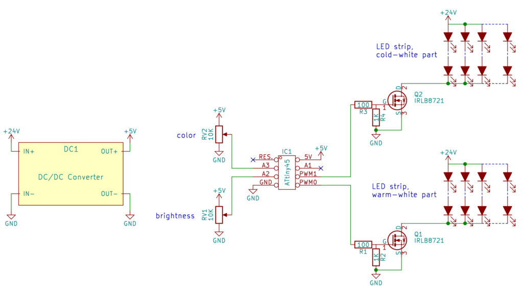

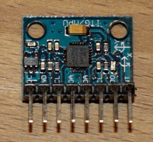
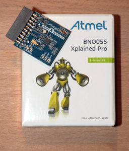
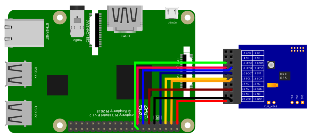
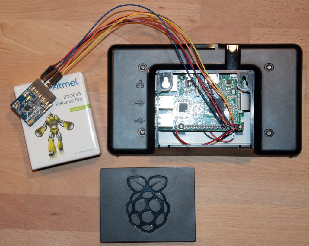


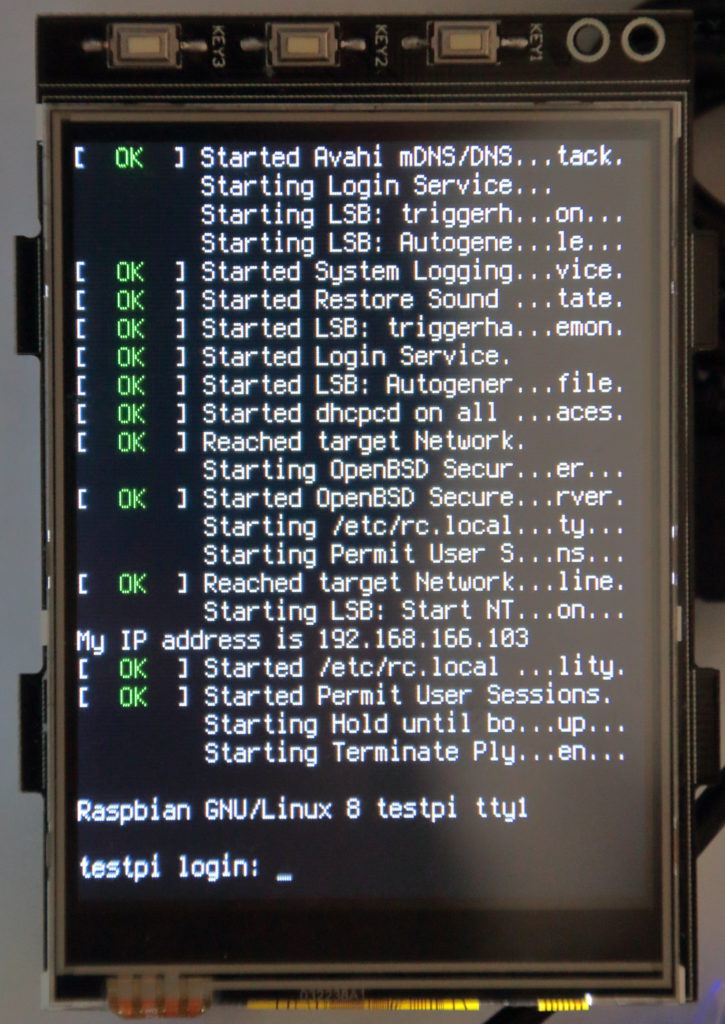
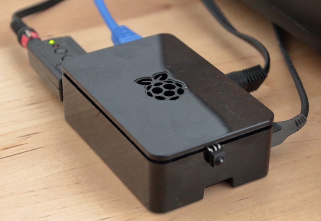
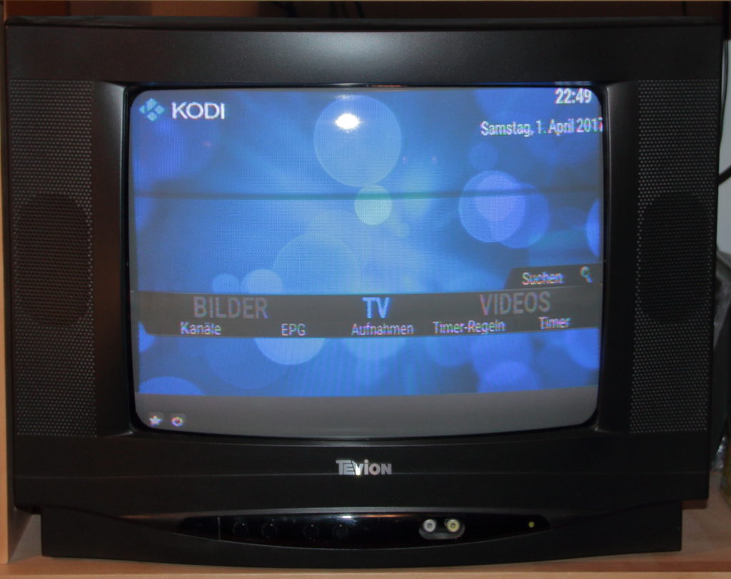

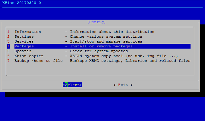
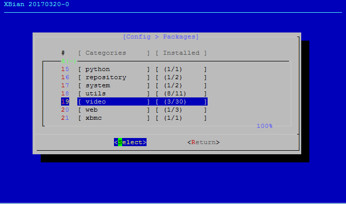
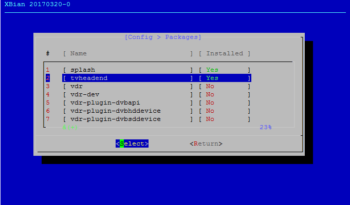
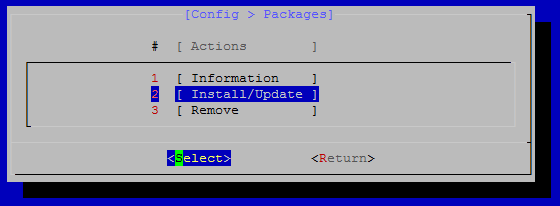
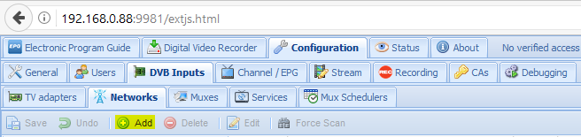
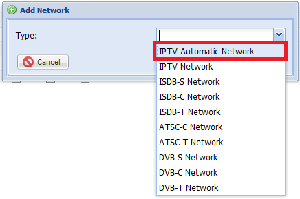
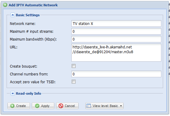
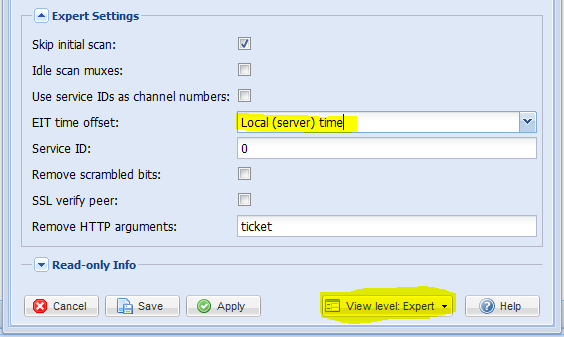
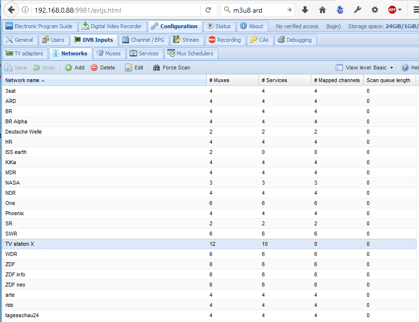
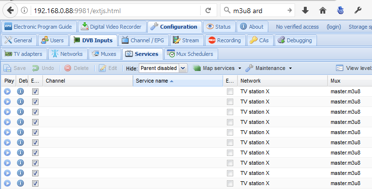
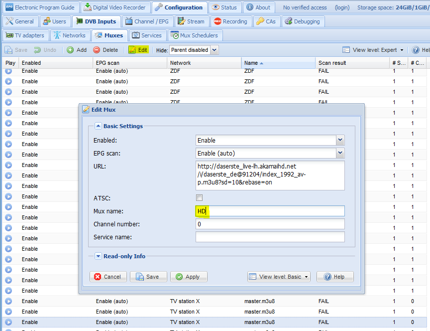
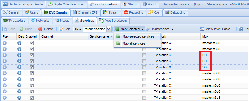
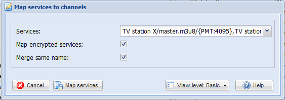
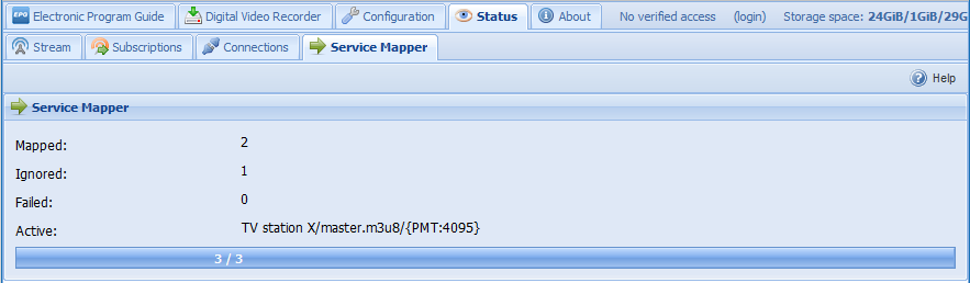
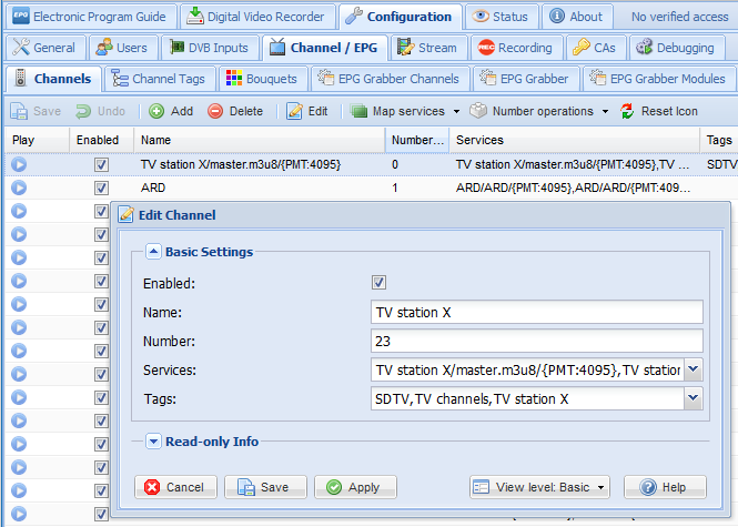
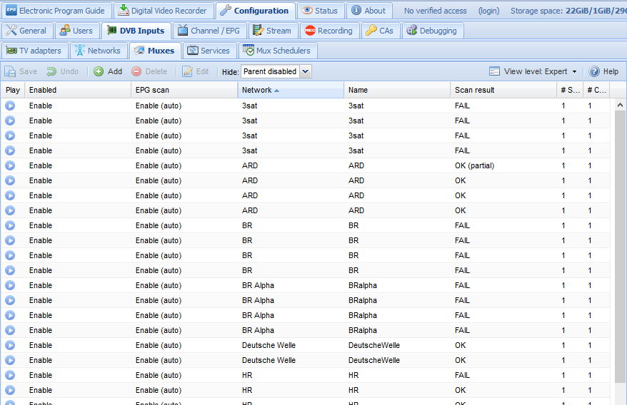
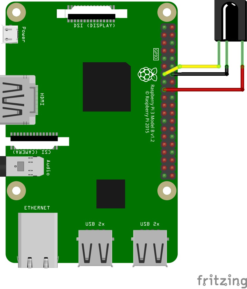
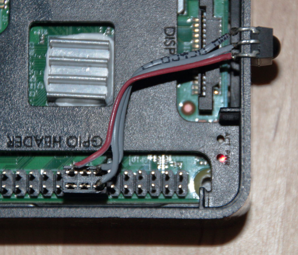
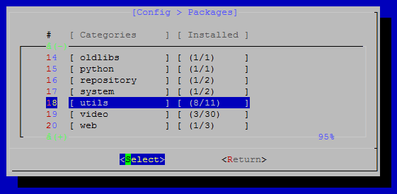
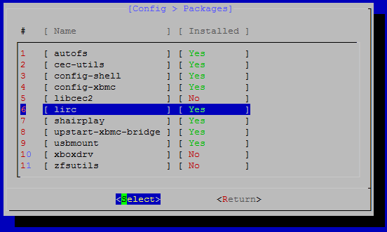
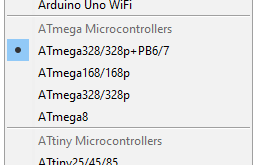
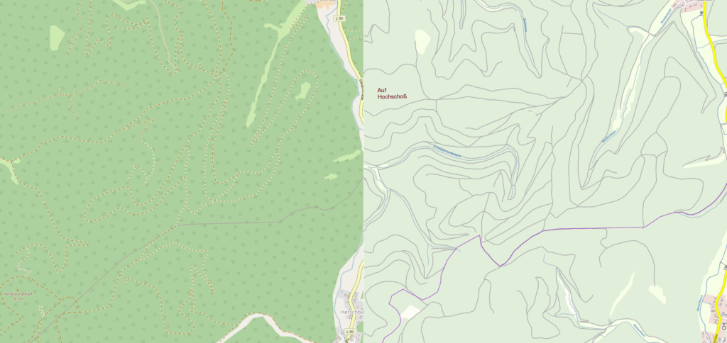
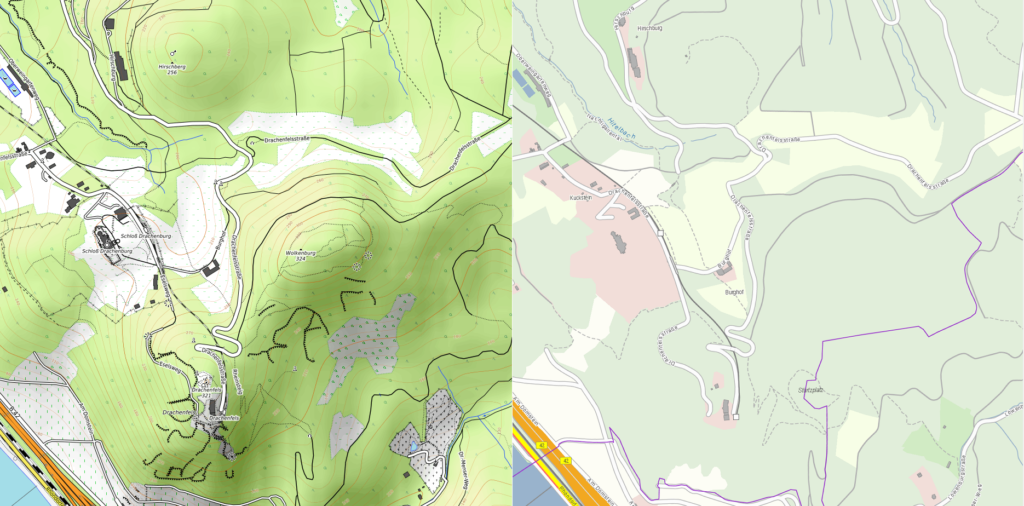
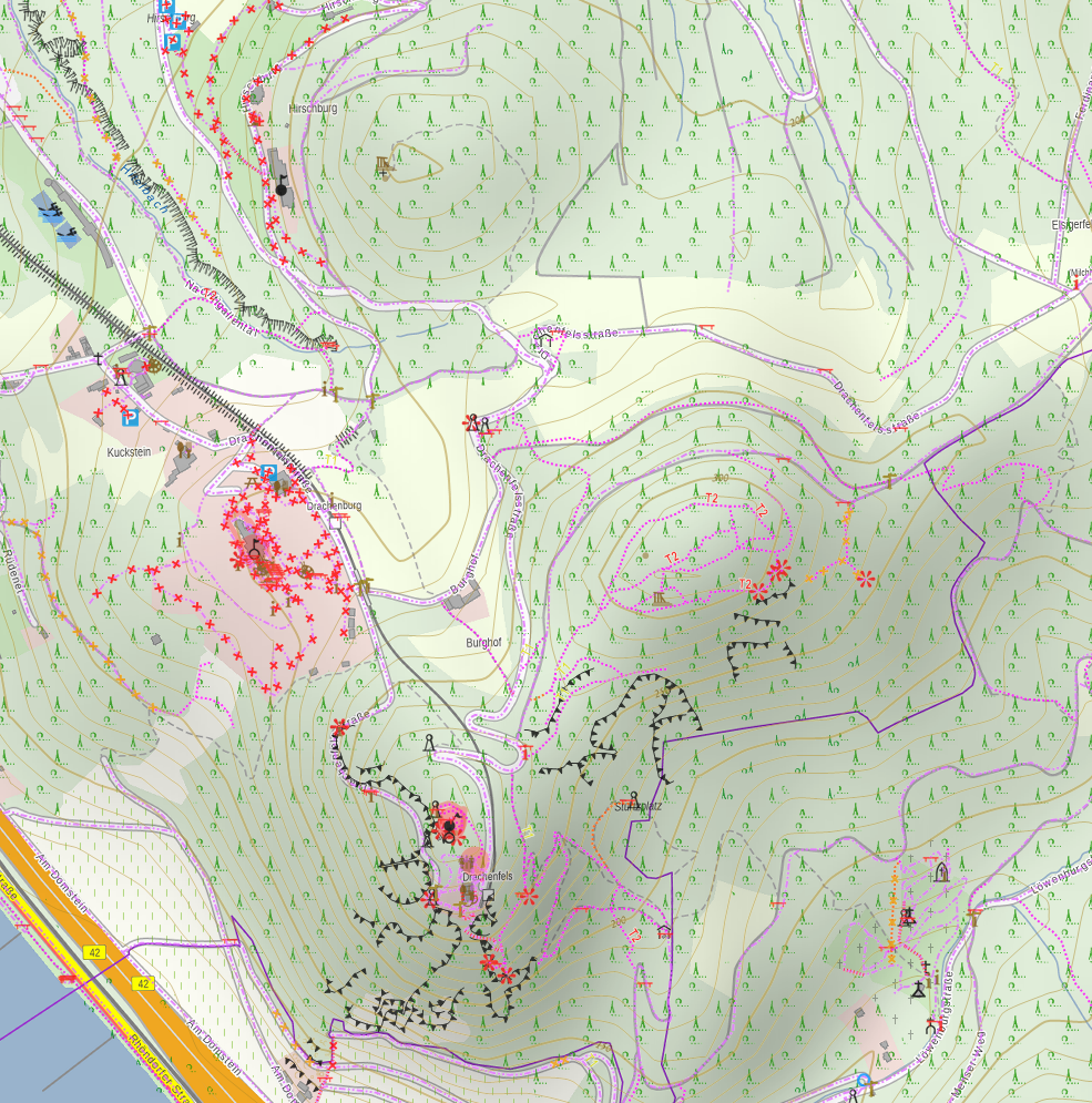


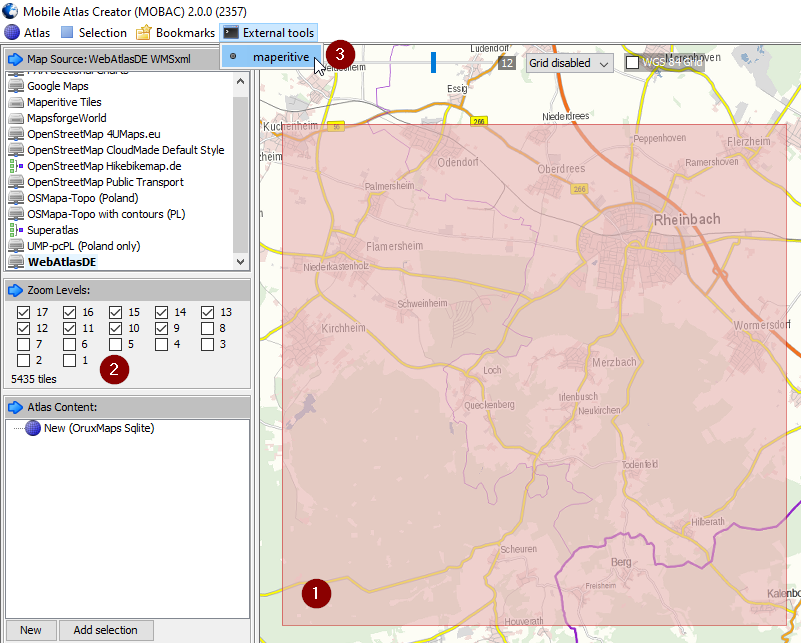


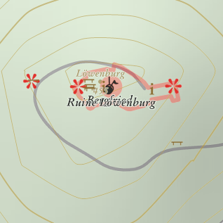
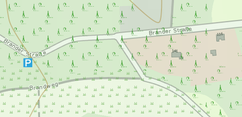


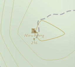
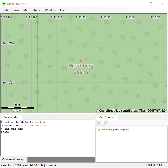
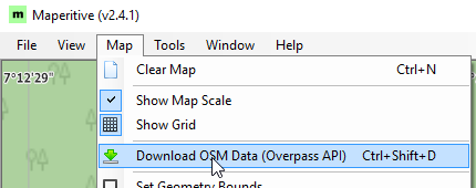
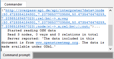
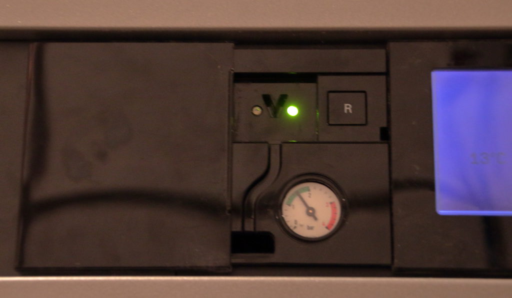
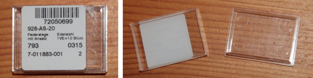
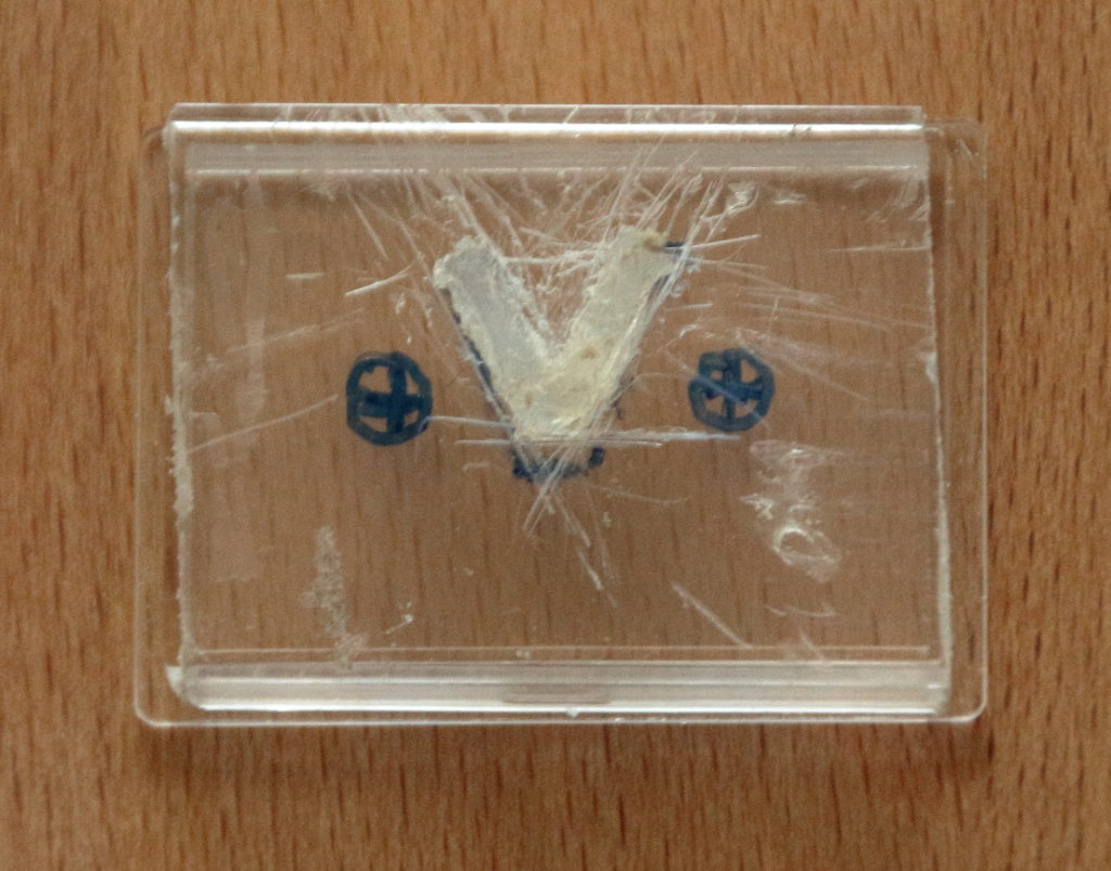
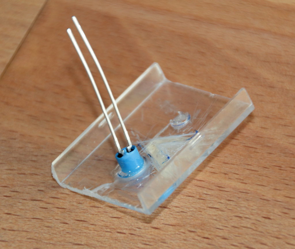
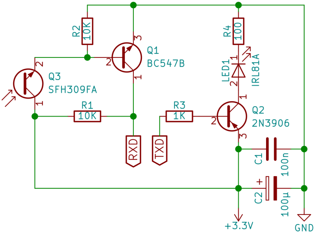
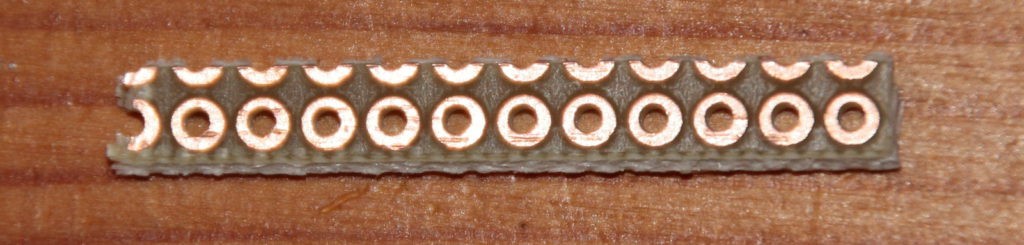
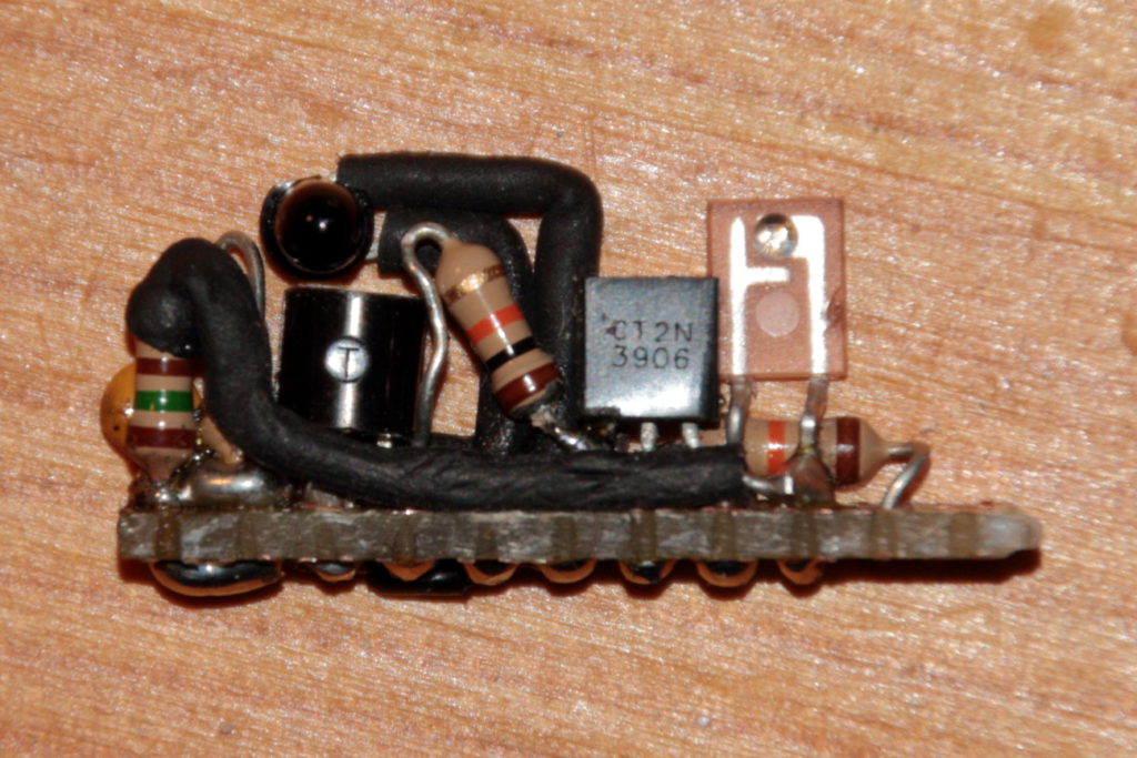
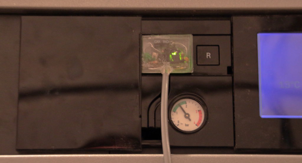
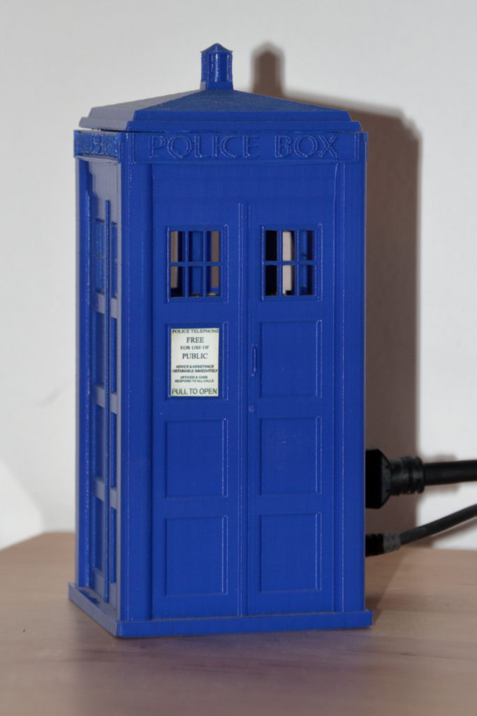
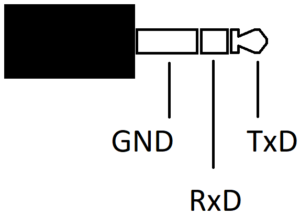
 Most volumes are mounted read-only, and so far I did not try to change anything about it. Needless to say that you are one wrong command away from bricking your TV here!
 So I’m stuck here at the moment… So,
 I just use the nylon lever to block the compartment lid directly – its stable enough.