The approach for creating feature-rich hiking maps described in my earlier post was limited in area, since it uses the Overpass API to download OSM data. The Overpass API has a restriction with regard to the amount of data downloadable in one go. In this post I describe a way to download a much larger area if needed, using the PBF files available from Geofrabrik and processing them with Osmosis.
Motivation
Me living in the Cologne-Bonn area, I love hiking in the Eifel, the Rhine and Mosel valleys, the Hunsrück and in the Westerwald. These are relatively close-by, attractive hiking regions with beautiful landscapes and quiet forests. For planning tours, I use my “Superatlas” – for details refer to my post “Creating the “Perfect” Hiking Map for Germany and other Countries”. Unfortunately, it is not possible to download the whole region mentioned from the Overpass API, but I wanted to have the whole area available in MOBAC, for spontaneous planning without first having to wait for the Maperitive jobs to finish. Doing one sub-area after another is no option, since in the overlapping parts you’d have “white spots” from the margins Maperitive creates.
Here’s how I was able to create a large area tile store for my favorite hiking region.
General Approach
My method is:
Download the PBF files that cover the required area using curl
Use Osmosis with a bounding box to reduce the data to the necessary amount
and to merge the individual files into one, which then I
load in Maperitive using the load-source command as replacement for download-osm-overpass
and do the rest the same way as before.
I also tried to reduce the amount of data by filtering the tags included, but in the end the reduction was not worth the effort, considering that I may even miss something due to an error made.
All these steps I put into a batch file that I include into MOBAC as external tool the same way as the other Maperitive-tasks, as outlined in the older post mentioned.
In Detail
N.b.: To fully understand everything here, you may need to read my first hiking-map post beforehand.
Getting the PBF Files
In the download-section of Geofabrik there are PBF files available for the whole world, updated daily. For Germany, you may go down to federal state or even district level. For the mentioned area above I use Hessen, Rheinland-Pfalz and Nordrhein-Westfalen (Hesse, Rhineland-Palatinate and North Rhine-Westphalia). Download may be done e.g. using curl, wget or PowerShellInvoke-Webrequest cmdlet. The latter has the advantage that nothing needs to be installed since it is part of the OS, but I found Invoke-Webrequest surprisingly slow. So I went for curl. Commands are straightforward (Here for Hesse):
(Replace <Path-to-curl> and <PBF-Path> with values for your environment)
Reduce Data with Osmosis
The most recent version of Osmosis can be downloaded here. Osmosis can consume all current OSM data formats including PBF, process them in many ways and output the processed data again in OSM data formats. Cool stuff, thanks to the authors! It requires Java.
What I do is:
Read in the first Geofabrik-PBF
clip it via a bounding box
write it to a temporary PBF.
Now with each next Geofabrik PBF, do the following:
You may do all this in just one Osmosis-run as well, putting all –rb … –bounding-box … parts into one command line (each –rb needs its own –bounding-box!). I found it a bit more easy to maintain the other way.
Optional: Tag-Filtering
You may even reduce data further by doing tag filtering. If you use my Suparatlas maperative rules, the Osmosis command would look like this:
Please note: You’ll need to read in the source PBF twice, since the first filter will lose all ways, the second will restore them, and only them. For details refer to the Osmosis Detailed Usage pages.
I did not use this in the end, since the data reduction was something of about 10% only, and I am afraid that my filters may filter something I’d like to keep in the end. Also, when changing my rendering rules, I would need to think of updating this also.
Changing the Maperative Command File
The only thing to change in the Maperative script file if to replace the line
download-osm-overpass
by
load-source <PBF-Path>\myregion.pbf
And that’s it – you’re done!
MOBAC Batch for External Command
Here’s my batch file – make sure to replace the path-placeholders:
<Path-to-curl>
<Path-to-Osmosis>
<Path-to-Maperitive>
<Path-to-MOBAC>
<PBF-Path>
Also, put in the download links for your regions and add/modify the Osmosis commands to pick up those files then!
Due to whatever reason the Osmosis-commands need their own shell (hence cmd /c …) – otherwise, the MOBAC batch would just stop after the first Osmosis-part. I guess it’s because Osmosis is wrapped in its own batch file.
On my five-year old 16 GB Core i5-4590 @ 3.3 GHz machine, processing an area from Aachen in the top left to Worms in the lower right, which is an area of about 16,000 km², took that much (RAM did not be too important by the way):
Downloading the files: ~1 minute (Depends on internet bandwidth of course)
Processing the Osmosis tasks: ~5 minutes
Loading and rendering the result PBF in maperative: ~5 minutes
Creating tiles for zoom levels 9-17: 9 hours
Resulting tile store: ~16 GB in ~800,000 files
So this is certainly not running on a daily basis here I guess my workflow will be: Use the large-area Superatlas with a seperate, “static” tile store for planning activities, and then for the actual hiking tour create a much smaller regional map, with up-to-date data, the “old” way using Overpass, to put on my smartphone. When in a hurry, I may use the “static” tiles for the smartphone atlas – better than nothing. Once every few months I’ll then update my static atlas.
Limitations
While the area limitation of Overpass is now overcome, I’d still not reommend to create a smartphone atlas from such a large area. The tile download from WebAtlasDE may still take ages, may upset the service provider, and the resulting file may be that large that the smartphone may struggle. Still, having the local tiles ready at hand is helpful already!
Credits
Thanks to the authors of curl and of Osmosis! Great work!
For a few days, this Blog will be “frozen”, i.e. you cannot leave a comment. I changed my web hoster, and until everything is migrated, nothing must change. I expect this to be done by Sunday May 19th latest.
Not being happy with a few things on my Sharp LC-24CFG6132EM smart TV, I decided to dig deeper, hoping to find ways to reconfigure some settings. While I not achieved that goal yet, I at least managed to gain root access to the Linux running on the TV. Since the TV set is based on a MStar product, I suspect that my procedure will work for any MStar based TV, at least those manufactured by UMC, which for Europe own the brands of Sharp and Blaupunkt. So here I document the procedure.
Disclaimer: The procedures given here potentially may render your TV useless! Follow the instructions at your own risk! There is no official support for this by MStar, UMC or Sharp, and the settings you gain access to, potentially may brick your device!
To skip my usual bla bla in the beginning, you may directly go to
From my earlier blog post you may have learned that I was watching TV with a pretty old SD CRT TV. But two things “forced” me to upgrade: Many TV shows nowadays assume that you have a hi-res TV, and many text inserts are too tiny to read on a SD TV. This sometimes considerably spoils the pleasure. Second reason: The switch to DVB-T2 in Germany. My old settop box stopped working, and instead of buying a new one, my thoughts more went into the direction of a DVB-T2 capable TV. So I went for a cheap Smart TV, the Sharp LC-24CFG6132EM, which sports Full HD resolution at 24″ screen size – not easy to find other models meeting this spec’s.
Short Review of the Sharp LC-24CFG6132EM
Here’s the Pro’s:
FullHD resolution
Smart TV: Works really well with HbbTV and IPTV
Good panel: Viewing angle OK, colour nice, brightness good, reasonably black when black.
Surprisingly good sound for its size. Not something to write home about, but well enough. Still, I mainly use my Stereo for better sound.
Radio based remote, not IR – works “around the corner”
Slender design, unobstrusive
Internet browser OK, Youtube works, Apps from Aquos
Offers Miracast and DLNA client – but not really… (see below)
Here’s the Con’s:
The picture “improvement” ActiveMotion 100 creates in certain contrast situations red, black or blue blurs that are strongly visible. This is especially annoying in faces, where lips, nostrils and hair often create dominant red blurs. Actually, that’s the reason I started all the stuff this post is about.
Lousy, bug infested software – Miracast and DLNA are practically not usable
Slow to boot – needs about 1 minute to be fully up’n’runnin’
PVR function is “blocking”, i.e. you can’t already start to watch a recording while it still records. This is rather stupid, since timeshift works just well – its just a bad implementation.
Menu functions are blocked when watching IPTV – no way to adjust the picture or the sound (Volume works, but not much more)
And some minor things about bad UI design and bugs.
Mainly the blurs are extremely annoying – all the rest is not too important, I can cope with it. I contacted Sharp support, and after quite some back and forth, they told me: The blurs, thats a broken motherboard – just send it in for repair. Did so: problem persists – no surprise, since I am rather sure it’s purely software/firmware caused.
In the meantime a software update (v. 4.21) went online – which was not helping with any bug, but added new ones! IPTV, which worked well before, became instable like hell! Fortunately I had the old firmware (v. 4.05) at hand from my odyssey with Sharp support… Did a downgrade.
Contacted Sharp support again, and now they offer to switch off ActiveMotion completely (which – stupid as it is – is not possible from any user accessible menu!) – I need to send the device in again *sigh*. I will certainly do so, but first I was curious what I can do myself.
To summarize my review: Currently I’d not recommend to buy this TV. Hardware is decent, but software is really awful!
So, what can I do myself? Will I be able to switch off ActiveMotion myself? Thet’s the goal. But first, I was able to
Connect to the TV via Debug UART
The TV has a 2.5 mm jack (smaller than the standard headphone jack, which is 3.5 mm) labeled “Service”. Using my Oscilloscope and its serial decode function, I quickly figured out that this is the debug UART, running at 115200,8,N,1, with 3.3 V logic level. Here’s what goes where (please make sure that your TV has the same pin assignment before you follow me blindly!):
Debug jack pin assignment
So, using either a Raspberry Pi’s UART, or – as I did – a UART to USB converter with 3.3 V logic level, you can use the UART.
When you switch on the TV, you’ll see the U-Boot messages and some more. Still, more is possible, e.g.
Accessing the MStar Console
When the TV just switched on, start hitting Enter on your serial terminal. The TV will stop booting (no picture will come up), and you’ll end up in the MStar command line console. Type help to see what’s possible – and it’s quite a lot! I could not find anything there to directly influence ActiveMotion, but there are many commands that allow to modify the firmware partitions. I did not yet dare to fiddle around there, but perhaps it’s worth a try later. Some commands strongly suggest that using them in a wrong way may brick the TV, so be careful!
Not finding what I was looking for, I aimed for
Accessing the root Shell
From my excessice exchange with Sharp support I learned that pressing
Menu – 1 – 1 – 4 – 7
on the remote brings you into the service menu, which again offers loads of functionality, not all clear to me. Among these there are very useful settings like the overscan, and others I’d say are even dangerous, like the LVDS panel parameters – I’m nearly sure you can render the screen unusable switching the wrong parameters! So: Handle with care!
But this Menu also brings you to the root shell. Do the following steps:
Attach UART as given above and open serial connection
Use Menu 1147 to access the service menu
Navigate to DEBUG
Navigate to MSTAR FAC MENU → A new menu opens
Navigate to WDT (WatchDogTimer) and switch it Off (otherwise, the TV will switch off after a few seconds after entering the root shell, because some TV functions cease to work when the root shell is entered and the WDT will interpret this as malfunction to be resolved by a reboot)
Navigate to “Other” (in German “Andere” – hope the translation is correct – it’s below “PIP/POP” in my case)
Turn UART BUS on
Hit Enter on your serial session/terminal
That’s it, you’re in! You’ll see a nice root hash prompt, and whoami will tell you you’re root! RC and TV will no longer be responsive, but who cares Most volumes are mounted read-only, and so far I did not try to change anything about it. Needless to say that you are one wrong command away from bricking your TV here!
Last remark here: To restart the TV run command reboot, or to switch it off, run poweroff.
Modify Settings
I am not very far with regard to alter settings yet. Still, I figured out a few things: One interesting file seems to be /config/sys.ini. It contains several configurations, among them ActiveMotion. While it is a read only file with a CRC checksum at its end, from my Sharp support communications I learned that there is a file named UMC_KMODE.txt, and its contents, when presented via USB memory stick, directly is digested into this sys.ini on boot. You’ll even notice that boot takes longer with such a stick/file attached, and the UART shows quite some activity during boot. So here’s the UMC_KMODE.txt I received for my model from Sharp support:
So, when I alter e.g. ADVANCEDCOLOR or ACEPRO from 1 to 0, it goes into sys.ini! And – lo and behold – there’s a line ACTIVEMOTIONID! But, looking into the comments in sys.ini, you’ll learn that it can take values from 1 to 5 – but not 0! And indeed, a zero is just ignored So I’m stuck here at the moment… So,
Where to Go From Here?
I’ve just only started some internet research, and looking for “hacking MStar”, there is quite some stuff to be found:
And Kogan (never heard of it before) seems also to do something with MStar, and here you’ll find some report on hacking it even via network.
I am not sure how far I’ll go, but what I certainly will do is send the TV to Sharp and see if they are really able to disable ActiveMotion. before that, I’ll try to dump the whole firmware somewhere and do a before-after comparison.
I’d be happy to learn from anyone who was able to advance further than me – please leave a comment!
Update March 21st 2019: Device *trashed*…
I finally took the time to send in the TV set to have the ActiveMotion feature removed. Result: PST, which is the repair service for Sharp UMC, just wrote me a lapidar mail, that the device is beyond repair and was – trashed! They did not even ask for consent! They just trashed my property! I am shocked and was rather mad with them on the phone. It’s a bit like having your garage call to say that the motor of your car was beyond repair, so they just put the car into the scrap press. They could not even understand my anger, they just said: What’s your problem? You get the money back, and it was broken anyhow… I do not believe a single word. They just decided they can’t do the change and that it’s cheaper to end the process here. Thats doubly annoying, since I cannot find a new 24″ Smart-TV with FullHD anywhere… Ba*tards!
UMC_KMODE.txt
So one thing is worth mentioning still, because before I sent the unit in I played around a bit, and I looked closer into sys.ini. The remarks there suggested that I could set ACTIVEMOTIONID to anything between 1 and 5 (see above), listing a number of features behind the numbers. I tried every number, and nice enough, when you go above one, in the picture menu a new sub-menu appears called “Expert settings”. In there is more picture control, like color control, backlight control etc. However, ActiveMotion was still missing But ActiveMotion was less pronounced for any value above one, and the artifacts were more bearable. Another reason to be angry about the desaster…
I can only encourage you to put a modified UMC_KMODE.txt on a USB drive, let the TV digest it and enjoy the new menu. You can (and should) remove UMC_KMODE.txt after that, since the boot process is considerably slower with the file present. The new settings are kept by the TV after removal, so that’s fine. To revert to the old settings you’d need to present a suitable UMC_KMODE.txt again.
In order to prevent my venetian window blinds to go down on timer in front of my open window-style terrace door, potentially locking me out, I needed to know if the door handle was in the “open” position. However, I did not want to use a battery powered radio sensor, but the existing door open/close magnetic sensor in the door frame. Here’s my solution.
My venetian window blinds are controlled by a Raspberry Pi. When the sun comes around to our window front around noon, in summer I lower the blinds, timer controlled, into their sun-blocking configuration, i.e. down, but the blades horizontal so you can look through them. When – like these days – it is really hot, we love to be in the garden, but to avoid the warm air to get into the cool house, we pull the door closed. The handle is in “open” position, but the door snaps into closed position. The door is basically a large window, so it has no classical door handle, but a window handle that in addition to the “open” and “closed” positions can also be in “tilt” position, allowing the window/door to be tilted a few degrees to have some air ventilation without the door being really open. Now, if the timer triggers and the blinds go down, it may happen that we miss this and find the door blocked by the lowered blinds, more or less locking us out. I still can use my smartphone to open the blinds again, but I thought that it would be better to have the blinds not go down in first place.
When we renovated the house and alongside the windows, I ordered magnetic open/closed sensors for the windows and doors. The actual sensors (reed switches) are mounted in the window frame, a cable coming out hidden in the wall (see also sketch below).
Reed Switch mounted in the Frame
The magnet that operates the reed switch is mounted to the top rail of the window. Opening the window removes the magnet from the switch, so the switch goes from closed to open. This gives me reliable information about the window state, but I did not think of the above blinds/door-pulled-close-but-not-locked scenario, which would require me to also know if the handle is in the open position.
There exist sensors for window handles. However, if you do not build them into the frame before the window is put into the wall, it is rather difficult to add them later, unless you go for battry powered radio solutions. Which I do not like. Batteries are bad for the environment, and they fail you exactly when you need them most, following Murphy’s law to get empty at the worst possible moment (i.e. when you are in the garden and forgot both to bring your front door keys and the smartphone). Also, radio would require me to extend my purely cable based home information/automation system just for the stupid door handles.
Analysing My Options
All around the window are mushroom cams that slide into slot plates when the window is closed, making the window as difficult to break open as possible to be safe against burglars:
Mushroom CamSlot Plate where the cam slides into
When I move the handle, the mushroom cams of the lock mechanism are moving accordingly:
So I arrived at the conclusion that I’d need to query the cam position in some way close to the reed switch and conway this information down the existing cable. My first idea was to put a mechanical switch on the frame somewhere to the cam nearest to the reed switch, so that it is triggered when the cam touches it in “closed” position. Then put the switch in series with the reed switch, and be done. I unscrewed the reed switch, only to discover that the cable was too short to be accessed from the outside, and somehow fixated so it could not be pulled out even by a millimeter. Not an option after all.
Next idea was to connect the magnet to the cam or its rail, so that it moves together with the cam. Looking at some other windows in my house I found that in some cases the manufacturer already did exactly this, and that the rails that move the cams are sometimes accessible and allow the magnet to be screwed onto them. But no luck at my terrace door: The rails were of a different kind with no access to the moving parts, lest having a mounting thread to attach a magnet to.
So I fired up my 3D printer and printed a piece of plastic with a hole in it to put over the cam (represented in blue in the figure below). The plastic would then extend to reach the reed switch. I’d glue the magnet to the plastic bar at the position where the closed cam would have it right under the reed switch, but where it would be pulled away when the cam moves to “open”. Actually, that worked!
First Try
I thought: Nice, done! But only until I tried to put the window into “tilt” position. The slot plate was right at the position the cam pulled the magnet into when the cam moves to “tilt” position (see also photo below). The magnet snapped off the plastic and I was back to where I started from
…Failure!
Final Solution
The moving magnet still was the solution in the end. However, instead of having a plastic part on the top window bar moving along with the cam, I went for a plastic part that could slide along the frame and is pushed by the cam, but not pulled back and then too far. It is only pulled back into the “open” position by a tension spring (red in the image):
Final Solution in Closed Position,in Open Position,and in Tilt Position: No Problem!
This works really well since several weeks now!
Real Life
And here is how it looks in reality. Here you can see the tension spring mounted to the reed switch screw. You can see how close the switch is to the slot plate:
Spring Mounted
By the way: The tension spring was something I had lying around. I cannot give any technical details, but I guess there is no really strict constraint on the spring constant, size etc., just try whatever you can put your hands on. I guess an elastic rubber band might also work, but these age and break at some point. Still, imagine the tension of a medium elastic rubber band, and you get a feel for the spring I used.
Here’s the 3D printed slider with the magnet already glued into position. Finding the best position for the magnet was just trial & error, fixating the magnet with tape at various positions, closing the door and see if the switch triggers at the correct handle positions. Two things were remarkable: First: The magnet must not be too strong, otherwise the switch would not unlatch in open or tilt position! And: there is a bit of hysteresis when moving from open to closed and then back to open, so the switch-engages-point needs to be very close to the handle being all way to closed position.
3D printed Slider with glued Magnet
Here are two images showing the slider readly mounted:
Slider mountedSlider mounted (Edge-on view)
This really works well! I was a bit afraid that the slider might tilt and get stuck when moving back into the slot from closed to open, but the narrow space between frame and bar provides enough guidance to avoid this.
Make Your Own
Think that may help you too? You can download my 3D file here or from Thingiverse, but I guess you’ll need to create your own model, since no window is exactly the same. My 3D model is just for guidance, carrying my ideas along.
Slider 3D model
The slider model was created with Windows 3D builder, which again proved its ease of use and versatality!
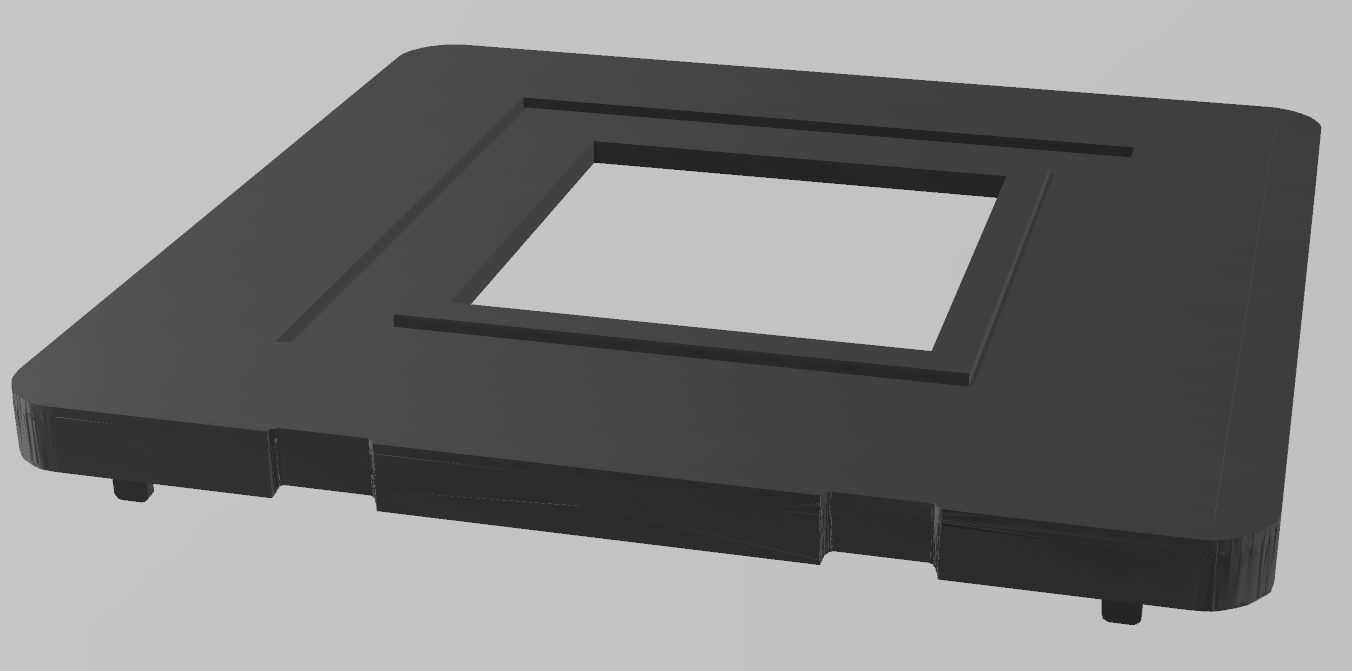
For a relative that’s paraplegic, I modified the housing of the remote control for the electric wheelchair wheels Alber e-motion M25 to make the usage easier. Mainly, the small housing was made thicker and larger for better handling. Also, one knob was moved to a different position.
The project is not very sophisticated, but I publish it anyhow – perhaps some other handicapped person can benefit from it.
Motivation
One of my relatives is paraplegic after an idiot, driving tired and falling asleep, crashed into her car. <Rant>He was an idiot doubly so, since at his side was his wife, not tired and perfectly fit to drive, but obviously he insisted on driving himself. Oh, did I say he’s an idiot?</Rant> Since then, she is sitting in a wheelchair, and has motors in the wheels to support her moving around. Recently, her old Alber e-motion M15 wheels gave up the ghost and where replaced by the newer model M25. Both models are controlled with a remote control, but the RC device has significantly changed between the models. My relative is rather unhappy, because with the restrictions the accident inflicted on her, the new, rather tiny RC was difficult to handle. The criticism was:
Keys too small
Keys too close to each other
RC too small to hold reliably in her handicapped hands
Bluetooth connection slow to start and not robust with other Bluetooth devices closeby
We contacted Alber, but they said: sorry, we cannot do different models for the RC, the numbers we sell don’t justify this. And sorry, you can’t have the Bluetooth protocols to create your own remote, they are to be protected as a security measure. I yet did not put pressure behind it – I guess, the latter argument is just self-protection. But they suggested: If you are technically versatile – why not alter the original RC? After all, not too bad an idea, so I went to work. Of course I cannot do anything about the stupid Bluetooth approach, but the other points I could address. So together with my relative we decided upon the target dimensions of the new RC and about key positions. The key size, if keys are seperated well, would be OK, and we kept it. Here’s the final outcome (she wanted it red…) as a teaser
The final RC
Realization
The following things needed to be done:
Design the new bottom part, the cover extension and the cover part for the moved knob – I did so using 3D Builder
Print it
Cut the new hole for the knob
Do the electric parts for the new knob position and the battery holder (The old battery holder is in the bottom part of the RC, which I replace by my new bottom)
Assemble everything
Designing the Parts
The following image shows the various parts. These are top to bottom, then left to right:
The original PCB – you can see the contact pads for the knobs
The battery cover and
The new bottom RC part with
six screw holes matching the original RC cover
two holes for the backside knobs for reset and pairing
four pads to hold the PCB in place
one large pad to hold the new contacts for the moved knob
the battery holder with contacts (spring and plate) harvested from a broken walkman
four screw holes to hold the top cover extension
a slot to put a thread through to attach the RC to the wheelchair
a place to put a nut into to match the fixing screw of the battery cover
The two backside knobs (unaltered)
The cover for the no longer used old knob position (misprint for illustration – the correct cover is already in place in the original RC cover)
A cutout from an old TV RC PCB to serve as new contacts for the moved knob
The power knob (unaltered)
The original RC cover (new hole drilled into and inserted knob hole cover)
The covor extension to match the longer bottom
The two knobs, which are cut in the middle so that the left part can be moved down
The parts for the new RC
The bottom part was straightforward, but still a lot of work, having several holes, a battery holder and pads to hold the PCB parts in position. The large pad middle-right is to carry the PCB cut from an old TV RC. The TV RC contacts match the contact pads of the moved knobs very well! If you build your own, you may need to adjust the battery holder contact slots, since you may have different parts there. Mine are from a broken, cheapo walkman, just a plate for +, and a spring for -.
The battery cover also was not too much of a hassle. If I would do it again, I might add some stabilisation: The one you see tends to bend a bit.
The cover for the no longer used knob hole needed a bit of precision, so the first print came out a bit to small.
The cover extension again was nothing very difficult.
Everything needed some precision, since the original parts that I kept set the scene. The original top cover I needed to keep, since the display is fixed into it and cannot be removed.
Printing
I printed the knob hole cover and the cover extension directly on glass to have a shiny surface that matches the surface of the original cover.
The bottom part I printed upside down to a) have a smooth matching border to connect seamlessly to the original part, and b) have some protuding parts nice and clean on the later bottom side. The drawback is that a lot of support needed to be printed on the inside, which in the end I was not able to remove completely. The inside looks a bit ugly in places, but this is hidden in the end, so nobody cares. I decided to print thick walls (2 mm) to have them mechanically robust. The RC may drop at times to hard ground, and I wanted the parts to survive such a drop.
The battery cover has no challenges when printing.
Cut the New Hole (Optional)
You of course only need this step if you also need to move the knob. If you are happy with the knobs, this can be omitted.
My girlfriend assisted me here, being a goldsmith she is used to such fiddly work. She used a handheld spindle with drills and sanding tools. Aside from the obvious hole, you need to carve a recess that matches the bulge that surrounds the knob. I forgot to take a photo, but you’ll see what I mean if you have your RC unassembled in hand.
The two knobs for power choice and brake behaviour are one piece of rubber, so I needed to cut them in the middle.
Electric Parts
Battery Holder
After inserting the contact plate and spring, I soldered wires from the contacts to the PCB socket of the old battery holder. I could not get a matching plug, and I did not want to cut the original one, so I directly soldered the wires to the PCB. Watch polarity, as far as I could understand the circuit, there is no protection against wrong polarity!
Knob Contacts
Putting the original cover in place, I adjusted the position of the TV RC cutout to be right under the new hole. There I fixated it with a generous amount of superglue. I suppose that should be stable enough, and as of now, the RC being in use a few months now, it’s fine. You need to figure out where to solder the wires to, and I also had to connect a few conducting paths, but this is easy to figure out. On the original PCB close to the contacs for the knobs there are squared test points (see photo above) to which I soldered the other end of the wire. I used thin, enamelled wire.
Assembly
I think it is rather obvious what goes where. Only remarkable things:
I used the original screws to attach the original top cover
I used M 2.5 screws to hold the top cover extension in place – no nuts on the other side, just screwed directly into the plastic (be careful not to overtighten!)
I used a M 3 screw and matching nut for battery cover fixation
At some places I put rubber to improve water tightness, although I do not think I achieved the same sealing as the original RC.
When everything was put together, I was happy to see that it still worked:
Ready assembled RC
The new RC is in use now since a few months, and my relative is happy(er) with it.
Make Your Own
You can download the 3D files here or from Thingiverse. If you need to modify the models and hit a limit, please get in contact with me, I can provide intermediate steps you may use, but which need a bit of explanation.
If you keep the knobs in the original position, you of course need not print the knob hole cover, and you can remove the large pad from the bottom part.
I wanted to have a floating table of contents for my posts, but could not find any free plugin that allowed me to do so. Using a combination of plugins, I created a floating TOC myself, which is not perfect, but good enough.
The Goal and Approach
If you look on the right of my blog posts now, you’ll notice the second sidebar widget to be the Table of Contents, and if you scroll down a longer post, you’ll find that the TOC becomes “sticky”, i.e. is available regardless where you scroll to. There are plugins that do this out of the box, and potentially even better, but those are all premium plugins that cost money. I wanted to see how far I might get for free, and succeded in creating my own floating TOC with free plugins and a bit of CSS.
Easy Table of Contents Plugin
The TOC itself is created automatically using Easy Table of Contents. It is customizable to some degree, the user may hide it, and – most important – it can be a widget, e.g. in the sidebar. This was important, because I use the
Q2W3 Fixed Widget Plugin
to let the widget with the TOC become fixed – it can be found here. This plugin combination already worked well enough, with the only problem that the homepage also displayed a TOC, which made no sense, as it showed the TOC of the post last viewed. So I needed to hide the widget on the homepage, which can be done using the
Widget Logic Plugin
which is a plugin that influences the display of a widget using some WordPress functions and logical operators.
Putting Things Together
First step is to add the TOC widget to the sidebar, which can be done by the standard customization functions of WordPress. In the regarding dialog you can now set a tickmark Fixed widget that makes the plugin fixed, i.e. it gets sticky as soon as it reaches the top of the browser window when the user scrolls down the post. Where exactly it stops and sticks can be configured, but the default values are already matching my taste very well, so I kept them. In the widget logic field you put !is_home() which says: Only display the widget if the current page is not the homepage.
TOC widget settings
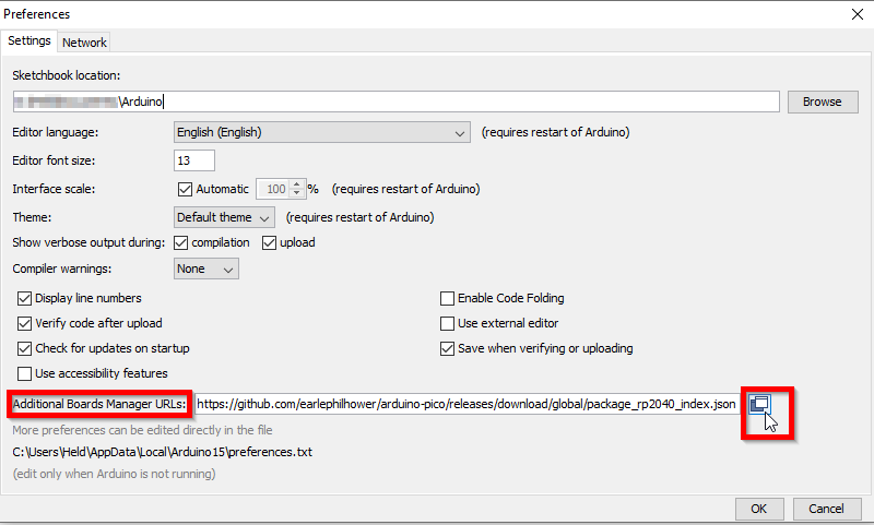
This is already very close to what I wanted, but since the widget looks exactly the same in style as other widgets in the sidebar, the display was confusing when the TOC floated above the other widgets. Also, in my theme (Amadeus), the other widet headings overlayed with the TOC, which looked ghastly. Last thing that I did not like: When the TOC is very long, it extends below the browser window bottom with no possibility to navigate there. All three issues can be addressed using just a bit of CSS. In the Additional CSS section of the customization page of WordPress, add
aside is the HTML tag of the sidebar widget, and ez-toc is the class of the Easy TOC plugin widget. The z-index puts the widget above the headings of other widgets, solving that problem. The box-shadow sets the TOC widget visibly apart from the other sidebar widgets. And the combination of max-height and overflow-y: auto causes the widet to not reach beyond the browser window bottom and display a scrollbar if needed. Now things look nice enough for my taste.
One thing remained: When reading a post on a mobile device, the sidebar is no longer a sidebar, but is just below the post. There of course a floating TOC does not make sense. Fortunately, you can define that the widget only floats if the browser window exceeds a given width. This was a bit of trial and error, rezising my browser window carefully until the sidebar jumped, and adjusting the Fixed Widget plugin settings accordingly. With the Amadeus theme the correct value is 973 pixels. This setting can be set in the plugin settings page of the Fixed Widget plugin.
Limitations
Not everything is perfect. When the widget changes from standard sidebar to floating, obviously the height changes as well if a scrollbar is needed – obviously max-height is ignored in sidebar mode. This on the one hand leads to a slight jump of the other sidebar widgets, and also creates a gap between the TOC widget and the next sidebar widget. However, in my opinion totally acceptable.
Second imperfection: When you scroll down the post, Easy TOC highlights where you currently are in the TOC. This however resets the scroll bar position for long TOCs. This is a bit nasty, but most of my posts will not suffer, since the TOC usually is not long enough to require a scrollbar.
It always bothered me that I could not modify the text (“Save my name, email, and website in this browser for the next time I comment.”) of the cookie consent checkbox in the WordPress comments section to explicitly mention that it uses cookies. I hate these “We use cookies – please accept” banners that bother you all the time, but of course I am really interested to stay compliant with GDPR and other laws. I found two solutions on the net:
The first is not update stable, since functions.php will potentially be overwritten by a theme update, and the second option considerably slows down the pages. And it is another plugin I need to hope that it does not contain a security issue…
Learning more about CSS, I found out that the modifications I wanted to have can be done using pure CSS, which I can add to the “Additional CSS” section in the Appearance menu of WordPress. Basically these lines did the trick:
I replaced the stock hotend of the Fabtotum Personal FabricatorHybrid Head v1 by an E3D Lite6 hotend (The full metal V6 should work the same way). In this post I describe the steps to remove the old hotend, get in the new hotend and the simple modifications to the firmware that were required.
A remark right in the beginning: Had I known how difficult and fiddly this project would turn out, I’d perhaps never have started it but would have gone for a dedicated print head with the E3D as others did, e.g. here. In the end I decided to remove the E3D again and build a seperate print head (I will write a blogpost on this as soon as I am done). The hybrid head is too crammed and strangely designed, it is a pain to fit something in that was not supposed to be there from the beginning. Still, I do not regret doing it – I learned a lot about the printer, and many things are still valid and needed for the new, individual print head.
If you are willing to remove the milling motor from the hybrid head, losing the milling capabilities, and can also live without print cooling (e.g. if only printing ABS), it is well worth to read this blog post, or also have a look at this page, but make sure to follow the thermistor steps I outline below, since they are missing in the mentioned page.
To skip directly to the parts interesting for you, use the table of contents below or on the right.
Why? Overheat Protection Killed my Hotend
The Fabtotum Personal Fabricator originally was a very successful Idiegogo campaign to build a CNC machine that could 3D print, mill and laser with a decent working volume. They fulfilled their campaign, and continued with an upgraded “Pro” model (Fabtotum Core PRO) which cost close to 3,000.- €. However, in the end the company did not make it, they filed for liquidation mid 2018. I got my printer a few months later on eBay from a backer for ~250.- € and took my first steps into 3D printing and CNC milling with it. In general, the machine is not too bad, but not too good either. I pulled my hair about it several times, but in the end I was able to get decent prints with PLA, PETG and PP from it. The main criticism I’d utter would be that it is very difficult to maintain because of some design decisions I’d call not so clever. I understand that the Pro model was much better in that regard.
Also, software was not fully mature, and in the end this caused me breaking my hotend beyond repair. Here’s what happened: I wanted to print something from polypropylene, which is possible with the Fabtotum – I successfully did this before. You need to go to the printer’s limits: I print it at 230°C nozzle temperature, and heated bed at 100°C, which are the max values for my setup. Now there’s one problem: When you heat up the nozzle and bed before the print starts, and then the nozzle moves in to start the print, the hot bed causes a sudden jump of nozzle temperature up to 240°C and even above. This causes the printer to trigger it’s overheat protection, and with a ghastly sound it moves the nozzle to one corner, stopping the print. A good countermeasure is to manually turn down nozzle temperature to ~220°C while it waits for the bed to heat up, but once in a while I forget this, stupid me.
One problem of the overheat stop is that the printer becomes unresponsive – you basically can’t do anything but powercycle it. When the interruption happened this time to me, I realized that from the printer UI the print is shown as “paused”, which I’ve overlooked so far. So my thought was this time: Why not just resume the print? So I clicked on “Resume print”.
And that was a stupid idea.
Actually, the printer resumed in a way: It switched on bed and nozzle heating again, but everything else remained stuck, no head movement. I started clicking around, trying to understand what was happening and looking if I somehow could get it going again, and while I did for 30 seconds or so, everything went hotter and hotter. I suddenly saw that nozzle temp was already at 300°C! I immediatly switched off the printer, and removed the head from it’s mount. But it was too late! The heatbrake plastic (yes, it’s plastic! I never understood why – looked stupid to me from the beginning on) melted, giving off the magic smoke, and the hotend was set askew:
The broken hotend
Actually, it looked even worse – the picture was taken not immediately after the desaster, but after me already working on the head for a while to prepare the replacement.
This certainly was beyond repair! And thats why I installed a new hotend.
Selecting the New Hotend
I first tried to find kind of the same hotend, since I remeber seeing such a plastic thing somewhere, but I gave up quickly, since my mind was already wandering in the direction of E3D, who have quite a reputation for good hotends. The famous Prusa printers are sourcing their hotends from E3D. Still, I wanted to keep the price as low as possible, since I backed the Snapmaker 2 campaign and hopefully will have a shiny new A350 3-in-1-CNC on my bench by July. Nevertheless I’d loath having the Fabtotum not in working condition, and also I’d need some prints before July. The E3D V6 has a perfect reputation, but in the end I went for the Lite6, mainly because it is cheaper. The spec’s are similar to the old, broken hotend, which not only holds true for the temperature range, but also in terms of size. Or so I thought – it was not that easy, but I come to this later. So the Lite6 it was, and I stopped looking further. However, the V6 should work the same way, since it’s dimensions are comparable to the Lite6. The Lite6 could still suffer from overheating, but all that will happen is that the PFTE liner will degrade, and that’s easy and cheap to replace.
Removing the Old Hotend
Basically, all that needs to be said is well said on this page (Only thing I did different: Did not use a Dremel, but a plain metal saw, sawed the plastic half through and then used two screwdrivers inserted into the plastic cavity and applied enough force to break the plastic tube at the sawed point), or on this page. Take care to not cut the heater and thermistor cables too close to the PCB! You’ll later need them, and it is extremely difficult to solder them on later due to the metal plate right under the PCB. Also, try to be gentle with the plastic tubes that guide the filament through the upper head – you’ll use them later again and want them intact.
Actually, before falling back to this brute force method, I tried to dismantle the whole head in a more reversible way, but I did not succeed. I went as far as removing the rotor from the milling motor (which already is a feat), but then I was stuck – I could not figure out how to unscrew the next screws, the stator coils being in the way. I tried to find a way using the Fabtotum CAD files and analyzing them in the 3D online viewer (thats really nice having both the files and the viewer!), but I gave up in the end.
I finally scraped away the remaining glue, and here’s the result:
Off with the head!The hole cleaned from glue
Software Changes
While waiting for the E3D delivery, I delved into the software, since the hotend comes with a different thermistor, which is not directly supported by Fabtotum. However, this can be mended easily.
FABlin/Marlin/Totumduino Firmware Changes
The Fabtotum controller board is dubbed Totumduino, basically an Arduino-ish Atmel MCU with Arduino bootloader, connected to a Raspberry Pi via serial port (which is why you always need the Arduino bootloader to have serial programming available). On it runs a Marlin clone, named FABlin. It is easy to modify and update the firmware, and it is nearly failsafe – in case something goes stupidly wrong, there is a plan B in form of a direct programming port (ISP) on the Totumduino board, which worst case allows a “low level” flashing of the MCU. So don’t be afraid of this step. If you want to be double careful, remove any head and the bed from the Fabtotum. A malfunctioning firmware might cause uncontrolled heating up of that components.
I got myself in trouble here – why and how I solved it I explain in the Appendix. I’d recommend that you read it to know what the worst case scenario might be, and to understand your risk. However, if you follow procedure, I’d say most likely it will not happen to you.
The firmware changes are necessary to enable and use the thermistor that E3D supplies with the hotend and mainly follow the E3D Marlin firmware guide. If you are hestiant to do software changes but still want to proceed, another option would be to fit the original Fabtotum thermistor into the new hotend. In my case the thermistor was just the naked glass blob, while the E3D needs a capsule. I guess it should be possible to replace the thermistor in the capsule, as in the capsule a thermistor of the same glass-blob-build is embedded. Its glass hovever, high likelihood to break something here. I also learned that later incarnations of the original hotend came with a thermistor capsule – so you may be just lucky. If so, you can skip all the software changes below (both firmware and FabUI) and use the original thermistor (if it fits).
Here’s the overview of all necessary steps:
Download and install Arduino IDE (if you not already have it anyhow)
This is not the only possible procedure – look on the README.md of the FABlin repository if you’re interested, or look at the Opentotum version, which has an additional method using Docker. Opentotum is a second place the Fabtotum software and documentation is maintained.
In detail:
Download and Install Arduino IDE
Download the Arduino IDE matching your system. As of writing this post, current version is 1.8.10. In some pages you may find references that you should use an older version – I had no problems whatsoever with the current version. Run the installer – that’s it basically.
Download/Clone FABlin Master
It’s in a Github repository. Recommendation is to get your own Github account and do a fork, but I was too lazy and just downloaded as ZIP and unpacked everything in my home directory. When I did my mod’s, the version was 1.1.1.3.
Make Sure that All Libraries are There
More than one way to do this – if you want to know them, read the README.md in the FABlin repository. Here is what I did, since I already have Arduino IDE installed and use it for other projects also:
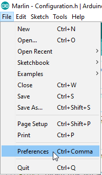
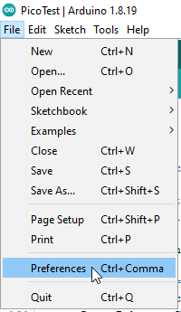
Identify your Sketchbook location – For this go to the Arduino preferences:
File > Preferences
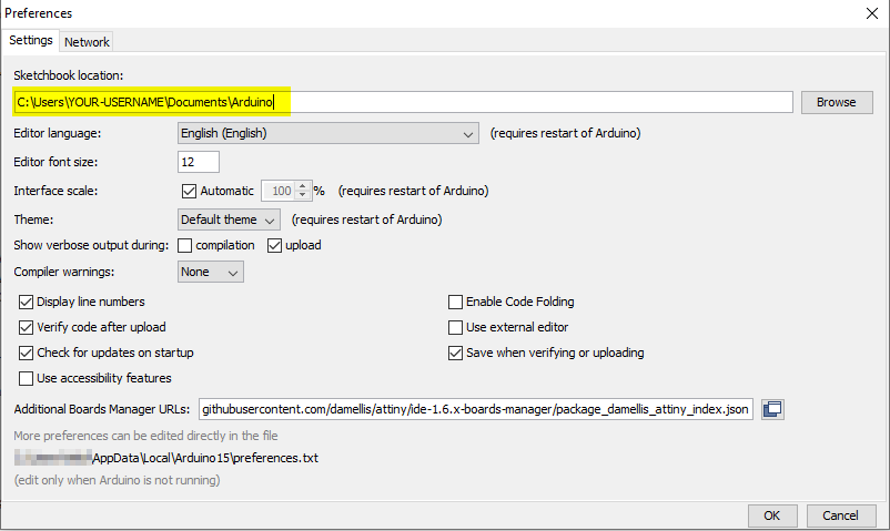
In the upcoming dialog you’ll find your Sketchbook location:
Find Sketchbook location
Go to <FABlin master directory>/libraries and copy the folder SmartComm into <Sketchbook-location>/libraries.
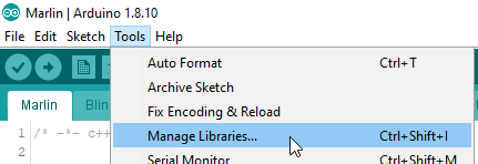
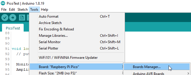
Install the TMC2208Stepper library – For this use Tools > Manage Libraries…:
Manage libraries
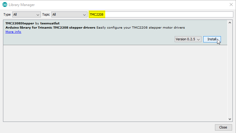
Then search for the TMC2208 library and select install:
Install TMC2208Stepper Library
Libraries are complete now.
Load Sketch
Navigate to <FABlin master directory>/Marlin and open the file Marlin.ino in the Arduino IDE (in Windows e.g. just doubleclick it). An Arduino IDE window should come up that has numerous tabs showing the source code.
The Arduino IDE with Marlin.ino opened
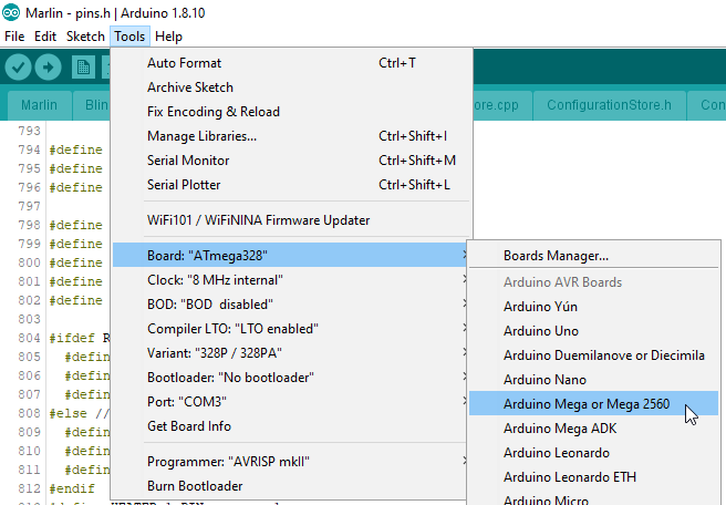
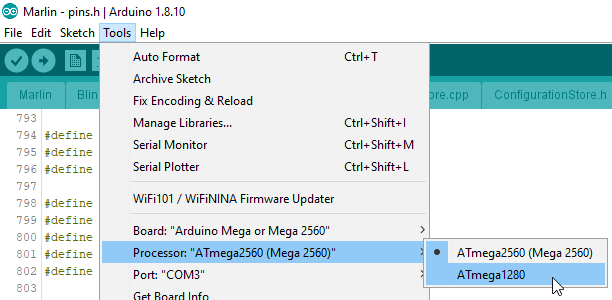
Select the Correct Board
Arduino IDE needs to know which MCU it is supposed to compile the code for. The MCU used on the Totumduino is an ATmega 1280. So go to Tools > Board… and select Arduino Mega or Mega 2560:
All necessary changes go into the file Configuration.h – locate the regarding tab and make the following changes (The line numbers I give were correct when I wrote this, i.e. version 1.1.1.3 – potentially they may change later, but the regarding sections should be easy to recognize. Honestly I expect the line numbers to be rather stable – since Fabtotum company ceased to exist there have been no changes to FABlin master branch any more.):
// USER CONFIGURATION:
#define THERMISTOR_HOTSWAP_SUPPORTED_TYPES ( 170, 11, 1, 171, 5 )
#define THERMISTOR_HOTSWAP_SUPPORTED_TYPES_LEN 5
#define THERMISTOR_HOTSWAP_DEFAULT_INDEX 0 // the index of within the supported types to which the printer will be initialised.
This adds the thermistor used by E3D (Semitec 104GT) to the supported ones – Marlin knows about it (the number 5), but FABlin had it disabled. The length of the array goes to 5, hence the change of the next line.
Some people suggest also to change the default index to 4 (selecting the Semitec as default), but I was reluctant, since I am not sure if this would not also affect the thermistor of the heated bed. I found a different way to change the default for the new head alone – stay tuned…
Another change to Configuration.h:
// When temperature exceeds max temp, your heater will be switched off.
// This feature exists to protect your hotend from overheating accidentally, but *NOT* from thermistor short/failure!
// You should use MINTEMP for thermistor short/failure protection.
#define HEATER_1_MAXTEMP 245
#define HEATER_2_MAXTEMP 245
#define BED_MAXTEMP 110
The E3D Lite6 can stand slightly higher temperatures than the original Fabtotum hotend. So the overheat stop will come later… N.b.: Later in the whole process I realized that this setting is potentially ignored: The device derives the overheat limit from the maximum head temperature + 15°C – will refer to this later.
If you use the E3D V6, adjust this line to the even higher temperature that hotend allows for.
It seems not neccessary – but I’ll monitor behaviour of the printer closely and may change the 0 to 5 later. The E3D Marlin page suggests it. Still, as far as I understand it, my other modifications later in this post should make it unneccessary to change the value.
Optionally, but recommended, finally make the following (or similar) changes to Configure.h:
// User-specified version info of this build to display in [Pronterface, etc] terminal window during
// startup. Implementation of an idea by Prof Braino to inform user that any changes made to this
// build by the user have been successfully uploaded into firmware.
#define STRING_BUILD_VERSION  "V 1.1.1.3e3d"
#define STRING_BUILD_DATE __DATE__ " " __TIME__ // build date and time
#define STRING_CONFIG_H_AUTHOR "FABteam/Hauke" // Who made the changes.
This allows you later to verify successful flashing of the firmware.
No other FABlin changes requried, you can now
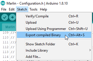
Compile
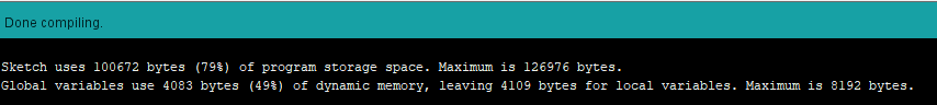
I use the menu item Sketch > Export compiled Binary since it directly creates the required firmware file:
Start compilation and export
If you did everything right, after 10 seconds or so in the lower window part you should see a message like this:
Success!
If you see orange messages – well, something went wrong. Read the messages and figure it out!
Now navigate to <FABlin master directory>/Marlin and locate the file Marlin.ino.mega.hex. Make sure to pick the one without bootloader! There is a second hex file with bootloader – using this would make plan B necessary, since the then two bootloaders mess up everything. And for plan B you’d need an AVR programmer – save the cost and use the right file
Locate the compiled files
I personally copy the file somwhere else to make finding it easier later, and I shorten the name, e.g. to Marlin.e3d.hex.
Upload File to Fabtotum and Flash it
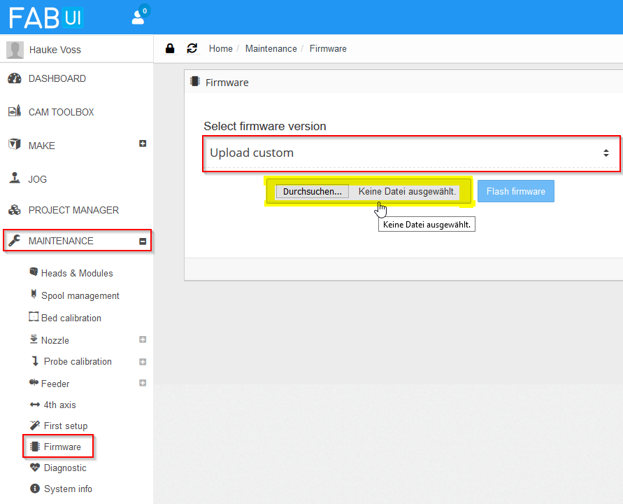
This hex file now needs to be uploaded and flashed to the Totumduino, which is easy using the FabUI (aka. the web interface of Fabtotum). Navigate to Maintenance > Firmware and choose Upload custom from the picklist. There will be a button to select the file to upload – but funny enough it does not work when clicking. What you need to do is click somewhere at the border of the grey area – I highlighted the “valid” areas in yellow in the image below:
Uploading the new firmware
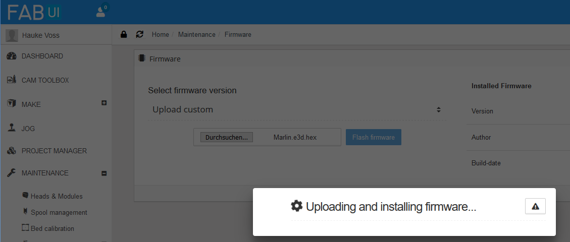
After selecting the hex file from the previous step, click Flash firmware. The LEDs of the Fabtotum will go dark, the update will commence, it beeps and the lights flash greenish.
Update in prgress
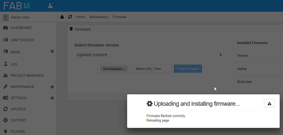
The firmware update takes about one minute, then you’ll be notified about the successful update and the controller reboots, lights turn white again.
Flash process successful
Control Success
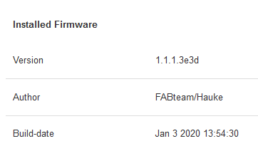
To control if everything went smoothly, go back into FabUI and navigate to Maintenance > Firmware – you now should see version and author as put into Configuration.h:
You did it!
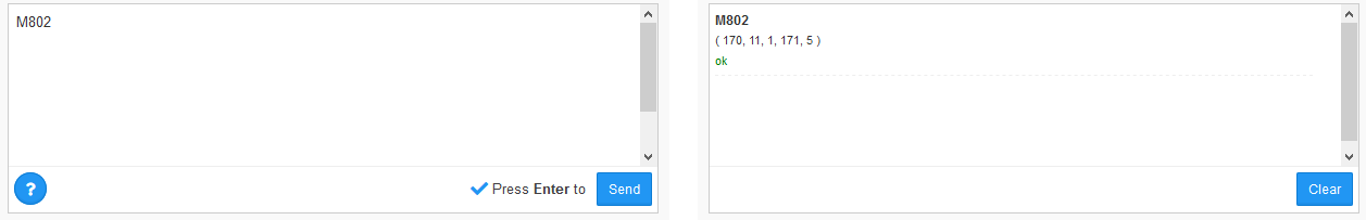
Now lets check if the other settings were accepted. For this go to the Jog page and issue the G-Code command M802, which gives the list of available thermistors – now there are five, including the new number 5:
The list of available thermistors – now including the “5”
I first thought that M801 gives the minimum and maximum temperature from the firmware, as it shows 245°C, but it turns out that this value is calculated from the maximum temperature of the head, which is changed later in the process.
You could also do M765 which would give you the firmware version, but we saw this already in the UI itself.
In addition I did some more tests, like jogging the head a bit, homing all axes, setting a bed temperature and see that this works, letting the milling motor spin, switch fan on and off and also re-attached the old heater block with heater cartridge and thermistor to check that controlling those works. All was fine.
Success! FABlin is ready for E3D!
FabUI Changes
As I continue to use the board and hardware of the hybrid head with the exception of the thermistor and hotend, I wanted also to use the existing hybrid head configuration profile. So what I needed was the possibility to select the now firmware enabled thermistor index 4 from the thermistor dropdown in the advanced head settings. With a few changes to the FabUI this is possible. My modifications are based on FabUI Colibri 1.1.6.
If you don’t want to meddle with the FabUI, I guess you have two options (which I both did not test, so try it out yourself):
In the Custom initialization section of the hybrid head include the following G-Code: M800 S4
This sets the thermistor index to 4. What you’d need to test: Is this overwritten by the thermistor setting in the profile at a later point? The thermistor selected in the profile basically ends up in a M800 command, and the question is what comes first: the custom init or the profile init?
In the Configuration.h also change lines 141/142 (TEMP_SENSOR_x – x = 1 or 2) to have value 4. This changes the default index. To be tested: is this overwritten later by the profile? I’d suppose yes. So most likely this won’t work.
Since the FabUI changes are easy, I’d recommend to follow me here.
To make the changes, I just SSH’d into the Raspberry Pi of the Fabtotum – use your favourite SSH client and go in via the IP of the Fabtotum. Login is root, and no password is required. I once set a root password, but Fabtotum just resets it to empty… I don’t like, but did not yet try to fix this.
I guess again it would be more proper to fork in Github and update FabUI the proper way, but I didn’t bother.
The line numbers again refer to the line numbers when writing this post (i.e. version 1.1.6) – may have changed in the meantime.
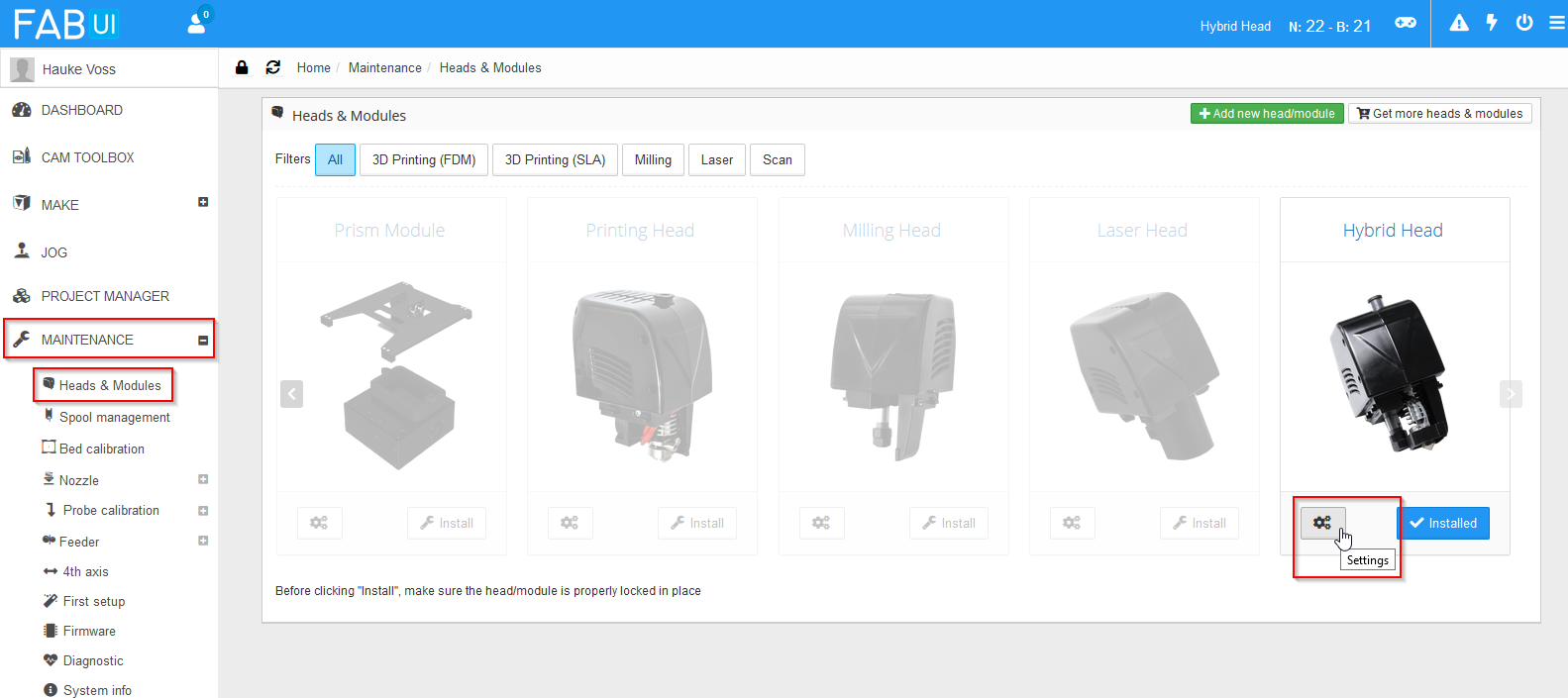
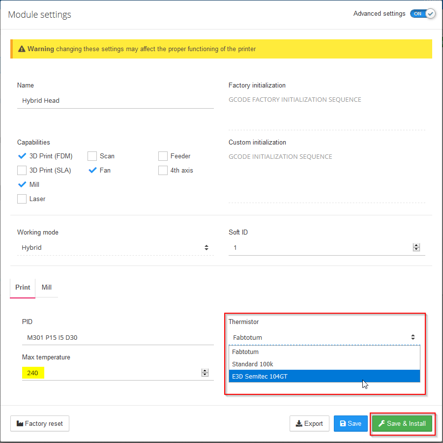
With above changes, I now can select the thermistor in the head setup. To get there, in FabUI choose Maintenance > Heads & Modules and select the settings for the Hybrid Head:
Navigate to head settings
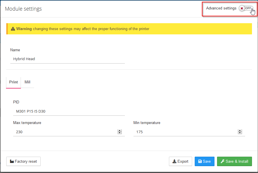
You need then to switch Advanced settings on:
Toggle Advanced Settings
Now you can pick the correct thermistor. Also set the new max. temperature – the E3D Lite6 can get a bit higher than the original hotend. If you have the V6, set the correct value for it here. Side effect: The overheat protection temperature seems to be hard coded to max. temperature + 15°C – After you changed the value here, M801 command will return a different value than before.
Adjust new hotend settings
Click Save & Install to let the changes take effect.
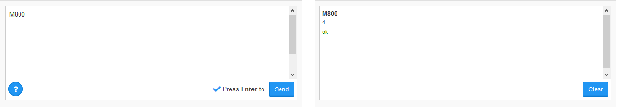
To check the success of this, go to the Jog section and enter G-Code M800:
The new thermistor index is there!
You will now get the value 4 as result – Success!
Please be aware of two things:
There is a “bug” in the FabUI: When you later open the head settings, the thermistor will always show as “Fabtotum”, regardless what you selected beforehand. In case you later make other changes to the head settings via FabUI, always make sure that you set the thermistor right again.
Second thing: All settings go into the file /mnt/userdata/heads/hybrid_head.json on the Raspberry. I played around a bit with it and had the idea to change the name of the head in there. This confuses the printer considerably, since name of the head and filename need to match. In other words, if you want to change the name, also change the filename. Also then create an image with the name that is displayed in the head selection window. It may be more complicated – I just started to understand the intricacies, but I could not care less, so I changed name and filename back to hybrid head, and stopped there.
After putting in the hotend provisionally it became clear that there is too little space! See the photos in the next section – you’ll understand what I mean. Only solution: The hotend must go deeper, sacrificing vertical build volume. Aside from that, another concern was that when running the assisted nozzle height calibration, the printbed might run into the now longer hotend, which for obvious reasons would be bad. To avoid this, furtunatly just the python macro that takes care of the calibration process needs one modification. I first could not find it, but with the help of Christopher Witmer from the Facebook Fabtotum group I was able to find the code and locate the line – Thanks! In the end my hotend did not protrude as deep as I was afraid of, so I might have skipped the modification, but to be on the safe side I changed it at leat a bit:
# Move closer to nozzle
    app.macro("G90",                "ok", 2,    _("Setting abs position"), verbose=False)
    app.macro("G0 X103 Y119.5 Z30 F1000",  "ok", 100,  _("Moving the bed 30mm away from nozzle"), verbose=False)
I double checked that this is enough: I did a height calibration and then an empty fake print without hotend to be sure that the calibration is used correctly in the print, which it is.
From looking around for the code I learned that the nozzle calibration goes into nozzle_offset in the head JSON file in /mnt/userdata/heads.
Getting In the New Hotend
Removing the Obstructing Part of the Base Plate
I would really have loved to skip this step, since the dimensions of the hole with 12 mm width would have been perfect to insert the E3D hotend into! However, despite trying hard I was not able to disassemble the unit to get the plate free. So in the end I took a metal saw and sawed the obstructing part away, now having a U-shaped gap to put the E3D into:
U-shaped gap after removal of metal obstruction
Be sure to clean away all metal shavings from the PCB!
(Optional) Fitting in the E3D – Temporary Solution
You can skip this step if you have access to another 3D printer and do the proper mounting later – for the proper mounting you’ll need to print a few parts. I don’t have another printer, so I first mounted the hotend provisionally to make my prints. (Please note, I do not recommend to do this – see my remarks at the end of this post)
The new hotend fits nicely in the U-shaped gap, but the rift is too broad so that the hotend is not constrained well vertically. I went for some rubber seals for cables, and cut one to fill the gap.
Rubber seals (right: The cut part)
It also insulates the PCB from the metal hotend. This was already enough to fixate the hotend snugly:
The hotend fixated with the cut rubber ring
To connect the thermistor, I used a two pin jumper connector, which is not perfect, but good enough:
Jumper pins
For the provisional mount I used the old heater cartridge – mainly because I was yet unsure how the cables would later run:
Connected thermistor and heater cartridge in place
Things are really tight now!
Fan collides with milling motor bearing
Putting the head together, it is even worse (I did not yet screw the head together in the photos – the gap in the head housing looks worse as it is):
Tight fit!
Still, I was a bit stupid here – rotating the hotend by 90° would have made it a bit less problematic, as you can see here.
Very tight! The plastic is in danger!
And the head mount adds to the problem:
In the printer – no place for the fan!
So, the E3D fan does not fit in. But the fan in the head does not put its full power on the heat brake – I decided that this must be enough and give it a go! The only thing you need to remember in this setup to always switch on the fan via Jog page whenever the heater is on to provide cooling to the heat brake.
I now followed the remaining steps in the E3D Assembly Guide. In there I learned for the first time in my 3D printing life of
PID Tuning
and that is very good! And with Fabtotum surprisingly easy!
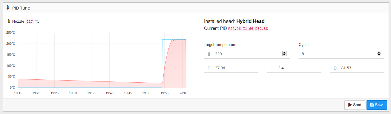
PID tuning is an automated process in which the printer establishes the thermodynamic paramters of the hotend in order to keep head temperature as stable as possible. For this, it does a number of heat/cool cycles and measures how temperature develops over time. In FabUI navigate to Maintenance > PID tune and select Start (did already in the screenshot, now says Abort):
PID tune start
Wait a few minutes, then save:
PID tune done!
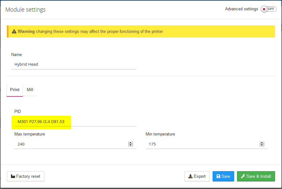
You can see the temperature wiggles getting smaller! The PID tune values go into the head configuration:
The new PID values in the head setup
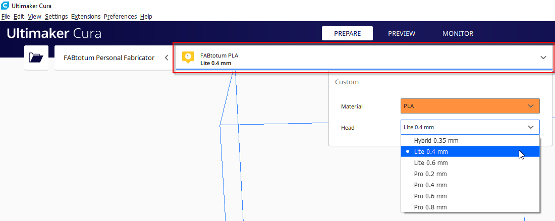
Change Nozzle in Cura
In Cura there are already profiles for different nozzle diameters, so that was easy – just pick it directly from the UI:
Selecting the 0.4 mm nozzle in Cura
Back in Business!
Time to start the first print! First of course nozzle height calibration, but off we go! I struggled a bit with bed adhesion in the beginning, but after a few fine tunings I was up and running:
First print with the E3D in place!
Print result was already very good, despite of missing print cooling fan.
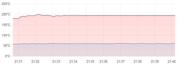
And here the effects of PID tuning were to be seen – the temperature stayed on spot for the whole print! Before, with default values, temperature was oscillating by a few degrees!
Perfectly stable print temperature!
Actually, if you do not need print cooling, you’re basically done now – let me again mention this page: It kind of stops here, but they removed the milling motor, which gives a bit more space. I suppose, milling functionality would still be given with my mod, but I never tried.
Parts for Final Mounting
Please note: I do not recommend to follow me through the rest of this. I think the basic idea is sound, but you lose considerably in vertical build volume and everything is a really tight fit. It works, but as mentioned before, I decided to go for a separate print head – blog post on this to follow. My starting point will be this thing on Thingiverse.
After preliminary mount it was clear that the hotend needs to go a bit lower to allow for the E3D clip-on fan to be somewhere and to avoid collisions between the heat sink and the milling motor bearing. Still, I wanted to be able to use the milling functionality. Admittedly, I most likely will not use it, since my first steps into it left me with the feeling that Fabtotum is not robust and powerful enough to do milling, but still, you never know. With the hotend sticking out further, the only solution could be that the hotend needs to be removable with acceptable effort. So my general design criteria were:
Needs to fit into the existing head
All parts including the clip-on fan need to fit in
Hotend needs to be removable (for milling) without dismanteling the whole head
I wanted to be able to pull the bowden tube from the head as with the old hotend – the E3D hotend itself makes this difficult
The old head was bad at overhangs – so I wanted to improve the print cooling
Here’s what came out (dark green/gray/white/black: PCB, metal part and obstructing jacks and bearing; yellow/white/red/orange: hot end and PFTE tube; purple: new part to go into the U-shaped gap permanently; olive/light green: two-part hotend carrier with air guide and screw-mount/dismount option):
The parts for the E3D mounting – what goes wherePut together (theoretical result)
My apporach is a fixed mounting plate that goes into the head. Into this, I screw the old bowden coupling from the old hotend. This allows me to pull the bowden tube like before. The hotend is put between two carrier parts, that snap into the aforementioned mounting plate and are fixed then by one screw. I also created an air guide for better cooling – let’s see how it performs. The air guide will be fed by the blower fan in the head, which in the original configuration seemed to have a mixed job: Cooling both the heat brake and the print. Since E3D provides a dedicated heat brake fan, I decided to only use the blower for print cooling – with a small exception in form of a gap where the air duct is connected to the mounting block: I bit of air should go through there, since I am a slightly concerned that the air duct may get too hot from the closeby hotend otherwise.
Small detail: The air guide has a notch to fix a zip tie to for cable organization.
To mount everything, you need two M3 × 12mm screws with matching nuts. Put one nut into the mounting plate before sliding it into the PCB. Use one screw/nut to fix the mounting plate using the existing hole in the PCB/metal part. Clip together the carrier parts around the E3D hotend top, slide it into the mounting plate and use the second screw to fix it tight.
I printed the parts with the provisional setup, and they came out just fine, with quite a bit of stringing. I used 100% infill for stability, and support everywhere – especially since I had no print cooling in place. Support removal was a bit of fiddely work, but came out well in the end. A bit of damage done when getting the support out of the airguide – which involved the careful use of a 3.5 mm drill, a flat craft knive and a long, thin screwdriver. A bit of superglue fixed the damage easily *phew*.
For everything new something old must go… In this case the bit of plastic of the head shell that worked as an air guide before:
Air guide cut away
Also, a small piece of plastic of the underside needs to go to make place for the mounting parts:
A small piece of plastic is also in the way
Parts Printed and Mounted
Everything becomes reality:
The parts printedNut and bowden coupling mountedElectric connections preparedHead partly mounted
I had to cut away some of the new air guide – I did not take the head mount of the printer into account properly.
Removing screw in the red circle allows to remove the hotend and start milling.Hotend unmounted, milling would be possibleFully mounted in the printer (View 1) – no cable manegement doneFully mounted in the printer (View 2)
Did I mention that it really is a tight fit?
Controlling the New Fan
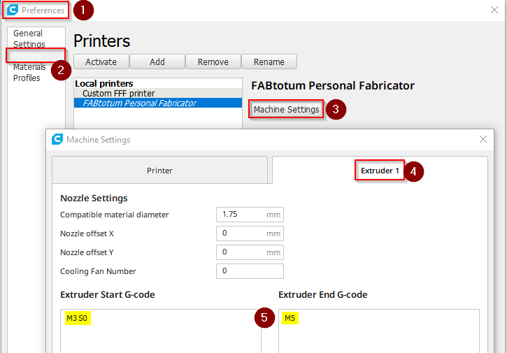
The 24 V fan for the heat brake that comes with the E3D heads can be controlled via the 24 V head voltage G-Code. With M720 it is switched on, with M721 it is switched off. In the hybrid head the 24 V also drive the milling motor, and the implementation has it that issuing M720 also lets the head do the beep-beep-beep cascade that you may know from the milling startup sequence or when using Jog to spin up the milling motor. In addition, it seems that the code in the hybrid head is somewhat weird – after several seconds the motor does another beep, and after two minutes or so it starts the motor – just so. No idea why… In the end I went for an alternative method: I used M3 S0 G-Code, which is “Motor on clockwise, 0 RPM”. To switch it off, it is just M5. I included this in the Cura Extruder profile:
Changing Cura extruder settings
After running some prints, I noticed a strange behaviour: after about 15 minutes the print head starts to emit regular beeps, created by the milling motor (It is always funny to see how they use the motor for making sounds!). Obviously the head’s MCU complains about having 24 V on, but not using the motor. This is really annoying, having your printer beeping all the time while your print runs! Of course, you can pause the print, send M5 and then M3 S0 again for another 15 min’s of silence, but really?
Update on Beeping
Again Christopher Witmer from the Facebook Fabtotum group was helpful here: He pointed me on the firmware for the milling head, which can be found on Opentotum. As it turns out, it is based on code written for controlling drone motors, and in the source code there is the routine that does the beeping – the comment tells what its intention is:
;-----bko-----------------------------------------------------------------
; If we were unable to start for a long time, just sit and beep unless
; input goes back to no power. This might help us get found if crashed.
It is to locate a crashed drone… Well, I’m sure my Fabtotum will not fly away Anyhow, I do not plan to go deeper in modifying the head software – it is in assembler language and I’d need to learn a lot, for limited gain. For the remaining prints, I’ll just detach the motor electronically, and reattach it when I am done printing.
At This Point I Stopped!
So, here I decided to stop and switch tactics to build a dedicated print head based on this Thing. With where I am I have the following problems:
Beeping. Solution: Change the ATMEL MCU code in the print head. Problem: I cannot find the original source code for modification. Alternatively exchange the 24 V fan for a 5 V fan put in parallel to the blower fan – supposedly much easier.
The bed probe is obstructed by my air guide. Solution: Modify the self-made head mount.
The air guide did not fit well and needed some cutting, making it inefficient. Solution: Change air guide.
Stability. My design is OK, but improvement for a better clamping of the head would be possible. Also, I might change for a bayonet coupling, since sliding in the PFTE tube is tricky with the current setup.
The clip on fan just barely fits in. Solution: Modify the mount to have the hotend another ~4 mm lower.
Loss in vertical build volume. With the 4 mm to be added, I’d be somewhere 2.5 – 3 cm short of before. Solution: None, impact: Acceptable…
Cable management: My current mount has problems getting all cabels properly out of the head. Solution: Change the mount, but it is not as easy as it sounds, since there is not much space after all.
Being generally frustrated by how tight and unwieldy everything is, I decided to stop here. I’ll keep you updated as soon as I have built my dedicated print head!
Still, it works:
“Final” setup up and running
That’s it for now – I’d call it a success, but not good enough after all. Still helped me to understand the Fabtotum much better. And I must say that FabUI is really a good interface – it’s a pity the company did not make it, I think there would have been much to expect from them!
Appendix: Broken Bootloader
After flashing the firmware the first time, suddenly I could not do it again via FabUI. The UI just got stuck during the process. The LED lights went dark only very shortly, then came back flashing green-ish, and nothing happened. Powercycling showed that the new firmware was not flashed.
Updating forever…
So digging a bit deeper, on the Raspberry there is a log: /var/log/fabui/avrdude.log – in there were tons of unhappy error messages like those:
avrdude-original: stk500_getsync() attempt 1 of 10: not in sync: resp=0x65 avrdude-original: stk500_recv(): programmer is not responding avrdude-original: stk500_paged_write(): (a) protocol error, expect=0x14, resp=0x03
Still, using avrdude to read from the Totumduino worked, so in general connection was there.
I found this page, but the suggested solutions did not help.
In the end I think the following happened, reading this post on Stackexchange: I thought I’d always need to use the hex file with bootloader, but the bootloader itself takes care that it is not overwritten while flashing, so I ended up with two bootloaders on the chip, which may interfere with each other in an unfortunate way. I tried to reproduce this by once again uploading a firmware with bootloader, but this time nothing broke. My explanation: First time I had two different bootloaders, the old from the time the Fabtotum was built, and the new one I uploaded, and these clashed. The second try I uploaded two identical bootloaders, which use the same memory addresses, commands etc. – so regardless which one is currently active, they work consistently together. Still, I may be wrong here, so there is a slight risk that something else might cause bootloader curruption.
In which case you need to do plan B (the author had a similar problem with a corrupted bootloader), although I did it slightly different. Important: The plan B procedure I just linked in misses the step of backing up and restoring the EEPROM – which does not seem to be a huge thing, but I still recommend to do that step.
The way I did it avoids all the hassle with unmounting fans and the Raspberry. For this you need an AVR programmer that can separate its own power from the Totumduino power (I e.g. own a Diamex All-AVR programmer that can do this), which allows you to have the circuit powered from the Fabtotum PSU instead through USB (which is unable to deliver enough power).
Here’s my procedure:
Open the left Fabtotum side where the Totumduino board is (Warning:This means that mains voltage is exposed around the power plug/switch and at the PSU terminals! Be sure that you know what you are doing, and do it at your own risk! Don’t touch mains voltage at any time! If you are unsure, disconnect power from the printer, unmount the Totumduino board and program it outside the printer or follow the plan B document, but include the EEPROM stuff below.)
Connect the programmer to the ISP in the right orientation (see plan B document for photos!)
Kill the first three processes that show up using kill -9 <PID>. Replace <PID> by the numbers at the beginning of the line (bold above, but numbers will be different in your case). Do one at a time (i.e. three kill’s).
Run the command /usr/bin/avrdude -D -q -V -p atmega1280 -C /etc/avrdude.conf -c arduino -b 57600 -P /dev/ttyAMA0 -U eeprom:r:Fabtotum.eep:i
This saves the EEPROM content (which will be lost in a minute) into current working directory (/root) – in there are some data about your Fabtotum (Serial number etc.). Fortunately the data in it is not crucial as far as I can tell, because I did not know about this step from the beginning and did not do it – my original EEPROM data is lost forever…
Send command poweroff – this is to avoid that the Raspberry interferes in any way – e.g. by sending a reset from its watchdog.
Now in Arduino IDE make sure that the correct board and processor is selected (see above).
Select Tools > Burn Bootloader (Warning: No confirmation dialog – this starts immediatly):
Burning a new bootloader
After this process (which just takes seconds) on the Totumduino board a LED will start flashing – that’s OK. It indicates that the Totumdiono currently holds no valid firmware besides of the bootloader.
Switch off the Fabtotum, remove the ISP cable and close the side again, no internal access needed any more.
Switch on Fabtotum – it will boot up, but the usual beeping will not happen, and the ambilight LEDs will not light up. Still, at some point you’ll be able to log in to FabUI again. Now follow the firmware procedure as shown above – in my case this worked now.
Log in to Raspberry
Do a ps -ef | grep py and kill the three processes that show up with kill -9 <PID>. Same as above.
Run /usr/bin/avrdude -D -q -V -p atmega1280 -C /etc/avrdude.conf -c arduino -b 57600 -P /dev/ttyAMA0 -U eeprom:w:Fabtotum.eep
This restores the EEPROM content. I must admit that this is untested for me, since I did not know to save the EEPROM in the first place. Untested in the sense that I tested the command, but am unable to tell if it really restores everything. It should however!
Restart Fabtotum. Should boot up as normal, with all blinkinlights and beeps. Sometimes boot takes very long, be patient! I guess the Raspberry is running a fsck.
Successful restore of EEPROM data can be tested by running G-Code commands M760, M761, M762 and M763. They should yield sensible values for the main controller serial ID, the main controller control code of serial ID, the main controller board version number and the main controller production batch number. If you get nonsense numbers (that sometimes look suspicously like unsinged maxint), EEPROM data is not correct, but this does not impair the functionality of the printer as I and some others can confirm (I suppose it voids warranty – but with Fabtotum corp no longer there, who cares…). You may put back into the EEPROM the factory settings (which are stored in Configuration.h) by issuing G-Code M502.
Last remark: There is a fuse bit in each Atmel MCU that says: Do not erase EEPROM on chip clear… (“EESAVE: Preserve EEPROM memory through the Chip Erase cycle”) I wonder why they did not use it if EEPROM data is in any way important… :-/
The Diamex/Tremex All-AVR programmer for ATmel microcontrollers comes as “naked” populated PCB, no case, no protection against shorts or other damage. I created a case for it, with the following design criteria:
Protection against accidental shots as good as possible.
Easy access to the jumpers that control the various operation modes.
“Park position” for the jumper that de/activates the external power (since it is often in “off” position and can easily be lost).
LED signals need to be visible.
Uses the existing mounting holes.
Here’s the result (in theory – created in Windows 3D builder):
All-AVR case in theory
Here’s how it looks in reality:
All-AVR case in reality
So using white (or transparent) plastic is enough to make the LED signals visible. Works nice!
Get the model files here or from Thingiverse. The screws to put it together are M2×18 mm with matching nuts.
A Few Words on the Product
The programmer itself caught my attention after I “bricked” an ATtiny 45 by disabling the Reset-pin, which I did because I wanted to use it as I/O pin. That’s basically OK, but I was then unaware that this renders ISP-programming impossible. To program such a MCU again, you need to use the High Voltage Serial Programming (HVSP) method, which requires different connections, a different protocol and the short application of 12V to the Reset pin to start HVSP. The Diamex All-AVR claims that it can provide 12V for ATtiny chips. However, the documentation is a bit unprecise – it is correct that the All-AVR can provide 12V, but this is to program the even smaller ATtiny 4/5/9/10 chips via yet another programming method, the Tiny Programming Interface (TPI). I reached out to Diamex, but they claim that it is not possible to alter the firmware of the programmer to support HVSP. I doubt that it is really impossible, but I doubt that I can get them to discuss this with me.
If you start looking closer, there’s a zoo of different programming methods for the ATmel MCUs – a good overview can be found here. So look closely before you buy your programmer!
Do I regret buying the Diamex All-AVR? Not really. It is not too expensive, it works directly off the Aduino IDE, and it is really fast. Also, it can provide an external clock signal for MCUs where you accidentily switched off the internal clock and do not have an external oscillator in the circuit.
I even got the thing operational using Bascom under Windows 10, which is a bit tricky, and I do not remeber the steps 100% any more. If you are interested, contact me, I’ll try to get the steps together.
For my “bricked” ATtiny MCU I will investigate other methods – the one that currently attracts me most is this one.
Alternative Case
rophos created another case for this. To me it looks like the jumpers are buried a bit too deep, but protection against shorts will be better here.
This is just a quick note that I updated my Tardis housing for my media center to now hold a Raspberry Pi 4. Files can be found on Thingiverse or be downloaded here. The new version features:
An improved POLICE public call BOX sign
A hole for a 5 mm LED in the top for a shining light
The necessary holes for USB-C, 2x Micro-HDMI and Audio out
A removable top
Here’s a photo (bad quality, sorry, will improve at some point):
The Tardis for Raspberry Pi 4 (bad quality – better to come)
Printed on Fabtotum Personal Fabricator with E3D Lite hotend and Renkforce blue PLA (can’t really recommend this brand…).
The top will need support, but make sure not to put support into the LED hole – I guess it will be very difficult to remove.
The LED to go into the Tardis light
I’ll update this post at some point with more and better images, and show the LED shining
Last remark: When I printed mine, I took wrong measurements – the HDMI slots were off by ~1 mm. The files are corrected, but I did not print it again. If you do, would be glad if you’d leave a comment if the holes are now correct.
Using ultrasonic distance sensors I monitor water levels for my garden irrigation system. I have an underground rainwater cistern and a wooden barrel as an interim water storage in the sun to have the water warmed up before use. I started off with the classic HC-SR04 ultrasonic distance sensor, but it turned out to be a bad idea for the warm water barrel: Moisture and temperatures up to 40°C in the summer sun made the sensor rot within half a year down to complete failure. I switched to AJ-SR04M watertight sensor (which seems to be very similar to JSN-SR04T which is often also mentioned on the internet). This has a higher minimum distance (~20 cm vs. ~2 cm), and a much larger opening angle (45° to 75° vs. 15°) as compared to the HC-SR04, and in this post I describe how I dealt with that.
The Situation
My underground rainwater cistern collects up to 3 m³ of rainwater, and I use this for watering the plants in my garden and on my balcony. Being underground, the water from the cistern is always pretty cold, and watering your vegetables with it slows down their growth, some plants (e.g. cucumbers) even developing a bitter taste. It is recommended to use warm water in “agricultural” gardening. So we got an old wine barrel and put it on top of our garage, where it sits in the sun most of the day. With an ATmega328P controlled magnet valve I fill the barrel up from the cistern. In order to control the valve, I need to monitor the water level, to start filling the barrel before it gets empty, and stop the fill before it overflows.
Reading a bit through the internet forums, many users claim that the classic HC-SR04 ultrasonic distance sensor does a good job, and survives the humid ambience for years. Its rather cheap, so I gave it a try. And it worked to my utter satisfaction in the beginning, giving robust measurements. But soon the measurements were a bit off on warm days, and it turns out that condensating water altered the characteristics of the sensors so that the reported distances were too large. At some point, the measuremnts were totally off altogether, and never returned to normal. I finally, after about half a year and a very hot summer, dismounted the sensor, and it was rotten and rusty! So I suppose it lasts for years in a cool environment, but up in the sun this is what you get very quickly:
Corroded sensor
The Watertight Solution
A bit more expensive, but watertight, are the sensors JSN-SR04T and AJ-SR04M (Here’s an in-depth comparison of the different sensor types, also with instructions how to access it from a microcontroller). Another advantage is that the sensor is detached from the control PCB, so it is easier to place the electronics away from moisture. And finally (not relevant for me), it has more operation modes, with onboard automatic measurement and transfer via UART. Still, since my whole code was already written for the “low level” communication with HC-SR04, I decided to stick with that mode, which the sensor is capable of also.
On the downside, the sensor has a larger minimum distance it can sense, the effective lower limit being at about 18-19 cm. The HC-SR04 works nice down to even only 2 cm. And with the barrel being ~60 cm in effective usable height, losing ~20 cm is considerable.
It seems that the watertight modules come with different kinds of ultrasonic converters, on a random basis. From the look they recycle sensors originally made for cars, and take what they get. Depending on which sensor you actually get, its opening angle is anything between 45° to 75° – much broader than the 15° of HC-SR04, which in a round barrel will not be helpful.
Here’s how my version looks like – you can spot the asymmetric outer shell which hints on being designed to sit in a car bumber:
The ultrasonic converter
Overcoming the Disadvantages
My first thought was to use a standard PVC tube to mount the sensor ~10-15 cm above the barrel. Turns out that the PVC tube reflects already so much sound, that I ended up always measuring the minimum distance. Bummer! So I took a piece of paper, rolled it into a narrow cone and used this with the sensor on the smaller side of the cone: Worked! Just a bit of an angle is enough to divert the sound so that only the desired signal reaches back to the sensor. Nice side effect: The opening angle gets very well constrained along!
Final Solution
I fired up my 3D workflow and designed and printed a cone mount for the sensor.
Dismantle the Sensor
I found that you can easily dismantle the sensor, which consists of an outer mounting shell, an elastic decoupling wrapper and the actual ultrasonic converter, which is much smaller than the whole contraption:
The disassembled sensor
I decided to take away the outer shell and design my final mount to have the sensor plus the elastic wrapping sitting in it.
The Cone Mount
The cone itself is quite narrow – here are its dimensions:
Cone dimensions
The resulting opening angle of the cone is ~10°.
And here is the part the sensor sits in:
The cone from above
When testing this, I got again always the minimum distance, meaning that the printed cone reflects back sound in itself. I kind of expected this, since the 3D print has a visible layer structure which makes the surface of the cone bumpy and rough. I considered sanding it or spraying something on the surface that dries smooth, but in the end I went for a very simple approach: I picked a sheet of stiff plastic (I think it was a laser printable transparancy sheet for old fashioned overhead projection), cut a piece out that I could roll into a cone and stick it into the printed cone. And that already did the trick! Here you can see the plastic sheet in the cone (ignore the strange shape of my base – it needed to be that way with my barrel):
Cone with plastic sheet
I fixated the sheet with a few drops of superglue – done! And in goes the sensor:
Ultrasonic sensor in place
Looking into the cone:
Sensor mounted (inner view)
And that’s it – works really nice, with solid measurements and a narrow opening angle! Long term stability remains yet to be confirmed…
In summary: As long as you’re OK with the sensor sticking out from your water container (or you have enough space inside it), the watertight versions of the SR04 sensor type are a good idea when used in humid environments, and you can overcome some of their disadvantages.
Make Your Own
Since your actual mount will most likely be different from my situation, I created a STL file only for the cone itself with the mounting slot for the ultrasonic converter plus wrapping which you can include into your project. Download it here or from Thingiverse.
From simple, standard electric cable I built a capacitive sensor to assess the water level in my water container. While the circuit was replicated from this blog (thanks for sharing!), I’d like to share how I built the actual capacitor.
The Situation
Only a few days ago I posted my successful implementation of an ultrasonic, waterproof sensor for measuring the water levels in my rainwater barrel. And while that post is still valid, the method turned out to be not as stable as I wanted. Again, condensation was the problem, drops running down the cone caused the sensor to show wrong levels ever so often. Also, I had problems with the fill hose drifting into the sound window at occasions, again spoiling the measurement. I guess with some effort all this could be fixed, but I was a bit fed up and doubted the long term stability of that approach.
With little hope I tried if an infrared distance sensor I had lying around might work, but as I suspected, water is transparent to infrared light, so this got me nowhere. I tried to put a ball into a tube, put the infrared sensor on top of the tube and let the ball float on the water inside the tube. But the opening angle of the sensor was too big, so it did only work for very short distances.
Came to my mind that I tried around with capacitive sensors for measuring soil humidity. The general concept (I followed this post past then) worked very well – I used double sided PCB material as capacitor – but I never could get it watertight. As soon as I inserted it into soil, I got a short. I tried different sprays and sealings, but I never got it right. I suppose epoxy resin should work, but that’s too messy for me. So for soil humidity I finally followed what many people did – I ended up using these cheap, pre-made sensors, which work decently well.
Elongated, Watertight Capacitor
So if I wanted to use the capacitive measurement principle with my barrel, I’d need a ~70 cm long, watertight capacitor, and I finally had an idea how to get one! I used a bit of standard, 1.5 mm² cross section power cable, which usually goes into the wall for the 230 V power network in your home – it runs under the type NYM in Germany – not sure how international this is. But basically the copper wire you use for home electricity – the actual cross section would not matter too much I suppose. Important however: You need solid wire, not litz wire – you’ll see why in a second. This wire is insulated with PVC, and that should be pretty watertight. For the capacitor I’d need two, not connected wires in parallel, which would leave me with an open end in the water, again difficult to get watertight long-term. So what I finally did is this:
Took a 3-wire NYM cable, the length of it bit more than twice my barrel height (~160 cm),
Stripped it off its outer insulation, so I get the individual wires,
Took one (the blue of course – it’s for water ) and bent it in the middle,
Now I carefully bent it back and forth, over and over again in the middle, until the copper wire broke (needs perhaps 20-30 times bending – and this only works with solid copper wire), while watching not to hurt the wire insulation,
Then pulled back the copper in the insulation on one side with pliers, so that a gap separated the now two copper wires,
Now put the two copper wires in parallel and fixated them with zip ties.
Here is my result:
Self-made elongated capacitor
A close look at the bending zone: The insulation is undamaged.
The bending zone where no copper wire is left in the insulation
For good measure, I also put a thick glob of hot glue around the end, also as mechanical protection.
Electronics
Since I could not remember the post I originally tried for my soil sensors, I googled again and this time found this post with a slightly different circuit, but the general principle is the same. The self-made wire capacitor probe is used with a NE 555 as an oscillator (the standard application “astable multivibrator”). The oscillation frequency depends on the capacity of the capacitor. Immersing the two wires into water would change the dielectric characteristics of the capacitor, which results in a change of capacity, which again results in a change of frequency of the oscillator. Using the ATmega 328P in my barrel water pump control, I measure this frequency using the pulseIn() function, and voilà, I could infer the water level in my barrel with a bit of calibration.
Circuit diagram
I expected that I’d need to play around a bit with the resistors to get into a frequency range that the MCU could measure (It could go up to somewhere near 100 kHz, although I’d recommend to stay about an order of magnitude below), but it turned out that with my setup having the original 470 kΩ resitors I was somwhere between 1 to 20 kHz, which is just right.
Important: Make sure to do your setup and calibration with all cables and wires in the final state – the capacitor alone in my prototype had me between 17 and 8 kHz (dry to immersed in water), but after I attached the wires to connect it from the barrel to the MCU housing, the added capacity from that cable pushed me down to 5.4 kHz and 2.3 kHz (dry vs. wet). Perhaps I should have tried to go higher again for a bit more resolution, but I did not bother. In the final setup I can measure my water levels in ~200 steps, which is more than sufficient.
What yet remains to be seen is the long term stability of this setup, but I’m rather optimistic here! Problem solved…
WordPress admins are currently sued for using Google Fonts directly from the Google servers without correctly informing users about the data collection by Google. I give a few hints on how to protect yourself against this. Disclaimer: I’m not a Pro in legal regards, so take everything I say with a grain of salt.
This morning I read this article on heise.de (German) – it seems that based on the verdict of the Landgericht München people try to sue WordPress admins for something between 100 and 500 €. The basis for this is that many WordPress themes (including the Zakra theme I currently use) use Google fonts directly from the Google servers. Doing this, your users leave traces on the Google servers, i.e. Google starts to collect data about your readers. If you fail to inform your WordPress readers about that, you may get into trouble.
While I hate this systematic skimming of money based on individual verdicts (“Abmahnwellen”), I do think that privacy of website users needs to be protected. The data protection laws might be inconvenient, but it is not that much effort to comply with their rules. Here are a few recommendations that I found useful when making my pages GDPR-compliant:
Deepl is an excellent translation engine to translate the Datenschutzerklärung into English. I cannot tell if the translation is still 100% safe in terms of legal compliance, but I decided that this is good enough for me. A few corrections had to be made, but I was surprised by the quality.
Depending on your use of cookies, you need a cookie consent collection. Since I do not use cookies that need consent (a matter that may be debatable), I do not have such a page and cannot give recommendations beyond that there exist plugins for that.
Use a plugin to remove the Google Fonts references to the Google server and serve the fonts directly from your own webserver. I use “Remove Google Fonts References” by Bruno Xu (thanks!), but this – as I just noticed – does not exist any more. But there are many other plugins in the wild! Google itself explicitly allows you to store local versions of the fonts. Make sure to check the specific license agreements for the fonts you use, but they are all very open.
Use a modern browser to check where your website actually takes your users to! When I created the privacy policy for my website, I realized that I promise a lot in there and made sure that I keep my promises. And here is how to check (as seen in Firefox – other browsers may look different):
Open an empty browser page, hit F12 and navigate to “Network analysis” (I could not get my browser to display the dev tools in English – so text might be somehow different).
Load your page.
Browse through the “Domain” column – if anything comes up that is different from your own namespace, you should double check if that page collects PII – if so, make sure that you inform users and that you are compliant with data protection laws!
Capacitative soil moisture sensors based on this DFRobot-design (and its successors) can be found in numerous blog articles about irrigation automation. For me, they do not work out for two reasons: a) A notable temperature dependency of the measurements, and b) a high failure rate after a few months to a few years. I decided to adopt the concept of my Simple Capacitive Water Sensor for a Water Container for soil moisture measurement, which turns out to work well.
First part is a bit of background – you may skip it and directly jump to the solution.
My Journey so far
The automation of the water distribution in my garden is one of my long-running projects, and a key element certainly is to measure the current state of the soil with enough precision to base the water distribution upon. So how to do it best?
Resistive Sensors: No.
The naïve first approach I jumped to (along with many others on the net) was soil electrical resistance measurement: The wetter, the more conductive. You do not need much: basically two electrodes that go into the soil, a resistor and an A/D converter, which most MCUs readily sport. Very quickly it becomes clear that this does not work well: The electrodes suffer from degradation due to ions emitted and from general corrosion, chemical reactions with other soil components, a change of soil properties by the measurement itself (ions wandering), and changes of the soil conductivity by e.g. fertilizers. First experiments quickly ruled this method out. So next idea you find on the net are
Capacitative Sensors: Yes, but…
The idea behind these sensors: The capacity of a capacitor changes with the electrical properties of the medium between the two plates of the capacitor. Water definitely does change these electrical properties. Only caveat: Measuring capacities is a tad more complex than the simple conductivity measurement above.
The DFRobot Approach: No.
But why develop something yourself when there is a cheap and easy obtainable ready made sensor for this? Enter the DFRobot sensor and its many, many cheap clones and versions. The creator of this approach obviously wanted to keep the A/D converter principle (as with the resistive sensing), and created a circuit that measures the capacity of the soil sensing capacitor, and converts this into an analog voltage, and obviously reasonably well. The basic principle is feeding a constant frequency into a RC low-pass filter, where the C is the soil capacitor, and then do a voltage peak detection. The change in capacity will reflect in a change of the RC filter cutoff frequency, and as a result more or less of the input signal goes into the peak detection circuit. Many bloggers report success with these sensors. So I obtained a few, put them to use and on first glance could confirm: Works! But using these sensors now for a few years, I’m less happy than initially. My problems:
Temperature Dependency
One thing that took me a while to understand was the sensor’s temperature dependency (I only today found this paper that confirms my observation to some extent). The sensors report higher humidity levels when cold as compared to warm or even hot. This does not strike as unusual immediately, because it matches expectations: If the sun burns down on your plot, you expect it to get dry. If night coolness comes in, with it comes dew, and therefore more humidity. But having now an alternative measurement principle (see below), I can see that the effect is artificial, and notable/relevant. My assumption is that the peak detector diode in the sensor’s circuit is the main culprit – these diodes have temperature dependent characteristics.
To quantify this effect: As to my observations, a change of temperature by ~10 °C changes the measurement by 20-30%! That’s not very helpful. And, on top of that, my feeling is that this behaviour is not very linear – at some point the measurement “jumps” up and the soil seems to get wet in minutes out of nothing.
Long Term Stability
The sensor part that goes into the soil is basically a coated PCB. The first batch of sensors I bought had a matte coating, and the first sensor broke after about two years. The second batch I got had a glossy coating, and these sensors last a few months at best. The coating at some point starts to flake off, exposing the underlying copper to soil and humidity. That of course renders proper measurements impossible. I guess sharp stones in the soil scratch the coating, humidity enters and the copper starts to corrode.
A Gallery of Failures
So here’s what I ended up with:
Capacitative Measurement by Frequency
The success with my Simple Capacitive Water Sensor for a Water Container encouraged me to try the same principle for soil humidity measurement. Again I used standard power wire (this time brown of course – it’s for soil ) as capacitor “plates” material, but unlike with my water barrel, I did not break the copper wire within the insulation, but used two separate pieces of wire and just bent them into U-shape, soldering both ends to the PCB (Watch the video below to see what I mean). I set the two U-shaped “plates” a few centimeters apart to allow a larger amount of soil inbetween as dielectric medium, hopefully getting a more stable measurement, that does not depend so much of how exactly I insert the sensor into the ground. Sampling a larger volume, hopefully would average out “local” effects also.
Using the two 470 kΩ resistors from the original design, in plain water the frequency goes from ~65 kHz (dry) down to ~25 kHz (wet). Looked about right, so I put it into soil. Turns out I might have been better of going a bit lower in frequency, but in the end I have ~100 levels resolution with the used ATMega 328P MCU at internal 8 MHz clock – good enough!
Testing the prototype
The sensor is now out in the wild since more than a year and works well enough. Sometimes I have a short “jump” in measurements, but I guess I can square this out by a bit more clever averaging in the code. The copper wires are excellent antennas I suppose, so the “jumpiness” is most likely some externally induced spike. Overall, I find measurements stable, and also not dramatically temperature dependent. I still seem to observe a slight tendency to report more humidity when it gets warmer, but the error in measurement is of the order 2-4% for 10 °C temperature difference, which is tolerable. Still, at some point in the future I’ll investigate this and maybe compensate this in code.
With the NE555 costing ~0.25 €, and the other parts even less, the solution beats even the cheapest DFRobot-clones I could find on Amazon.
In terms of long term stability a bit more patience is needed to give a final verdict, but I do not see what would break the water-tightness of the PVC coated wires. As of now, my sensor goes into the second year, and performs well. It encouraged me to replace all other DFRobot sensors that I still have in use by the same design, only upping the resistor. I’m now introducing one with 1.5 MΩ resistors, and will see how much this influences measurements.
Side Effect: Signal Stability
I did not have any issues with signal quality with my analog sensors (yet?), but the risk is there: If over time the contacts of the jacks show a bit corrosion, resistance of the junctions may change, and this will affect the analog voltages, and thereby the measurements. Measuring frequency is robust against such kind of electrical degradation.
Conclusion
Long-term stable, (near-)non-temperature affected soil humidity measurements can be done very cheap with simple-enough concepts – I will now replace my DFRobot sensor clones with the new concept. The key was the idea to use standard PVC coated power wire for the probing capacitor – I was stuck too much on the idea of using raw PCBs, which I simply could not get watertight. Glad I got the other idea
Make Your Own
For circuit design and code, please refer to my post Simple Capacitive Water Sensor for a Water Container – I would recommend to replace the 470 KΩ resistors by 1.5 MΩ, or even more, depending on the length of your wires. 1.5 MΩ works good enough with ~12 cm of wire (length measured after being bent into U-shape – so the wire itself is more ~25 cm).
Appendix
Of course the sensors get 3D printed housings, but I dived again into CNC milling my own PCB boards – must say that after getting past a few problems, I finally get decent results with my Snapmaker 2.0. Will perhaps at some point make a post about this. Until then the very short version: Use KiCAD to design your circuit and PCB, then use FlatCAM to create GCode for isolation routing, hole drilling and cutout GCode. You’ll find other tutorials on this aplenty on the web.
My Raspberry Pi 4 based media center has some issues, which I was able to resolve by switching to an Intel NUC8i3BEH platform. I was able to make the device quiet despite of its fan, and set up everything to have live TV and PVR, a web browser, Spotify and other DRM content in a very usable and performant setup.
The first paragraph contains a lot of opinion and bla bla – for the setup guide skip here.
Why a New Media Center Again?
Nearly 7 years ago I started playing around with media centers: the first one Raspberry Pi based, then using Le Potato because of the need for HEVC hardware codec, and, after being frustrated with the limitations of Le Potato, a journey back to Raspberry after the Pi 4 came out. I’ve always been focused on KODI centered OS distributions like LibreELEC or CoreELEC. With Raspberry Pi 4, I diverted from that path and used a native Raspberry Pi OS install and put on top of it the KODI package. There are three large advantages that come with that approach:
Full fledged web browser (close KODI, use Chromium or Firefox ESR on the standard Pi desktop) – and with that: easy use of the German “Mediathek”. The KODI plugins for this have been a slow and very unstable affair all the time.
Netflix, Spotify and other DRM content providers work just by installing the Widivine package – no tinkering with the cumbersome Netflix KODI plugin.
The freedom to tap into the full Debian software packages – no restrictions from the stripped-down and kindof locked *ELEC-distributions anymore. Allows e.g. the use of VLC player.
Still, some frustrations remained:
Closing KODI sounds easy, but KODI takes about 10 seconds to close down. Not a huge issue, but a bit annoying.
System instabilities: After closing KODI, sometimes the desktop was missing the Task/Menu-bar. Restart required… Very annoying.
Wonky playback in the browsers: With the hardware-decode optimized Chromium browser, most videos played without frame drops, but there were obvious difficulties with aligning the media framerate and the LCD monitor refresh rate, causing “micro-stops” in the pictures, e.g. when playing 24 fps video on the 60 Hz monitor. Workaround is to use the “Play in VLC” plugin. VLC does the job perfectly, but this really impacts ease of use.
In general, the desktop UI on a Pi 4 does not feel very fluid/performant – long wait times, sub-par page scrolling, laggy Spotify UI etc.
Bad reception of some channels with my WinTV dualHD USB DVB-T2 receiver: I live in about 1 km distance from the DVB-T2 broadcasting antenna and can actually see it from the windows of my living room, but still when receiving the 514 MHz multiplexer, I got signal problems in certain situations. I never figured out why this problem exists – I assumed it was power related and that the Raspberry was just not pushing out enough volts for stable operation, but even with a dedicated PSU for the USB receiver problems persisted.
Raspberry Pi 5: A (Potential) Disappointment
Enters: Raspberry Pi 5 – the surprise announcement gave me a short spark of excitement – I was hoping that with this incarnation the Raspberry would be powerful enough to give me a better general experience, and perhaps more hardware codecs, like VP9 or AV1 (like the Le Potato did). Turns out: Au Contraire Mon Capitan! They even dropped all hardware codecs except for HEVC! The engineers at the Raspberry Foundation claim that software decode is powerful enough, but with my Pi 4 experiences I had my doubts, and several forum posts and reviews seem to support my anxiety: Yes, it can decode quite a bit, but you need optimized software, must not get too demanding, and the CPU will have to do quite some heavy lifting. There are still reports of the Pi 5 dropping frames with YouTube 1080p@30 Hz videos… Honestly I do not understand the decision of the Foundation to drop the hardware decoders. Admittedly, the Pi 5 at the time of this writing is very new and we can expect quite a bit of development and improvements, but for the time being I felt strongly discouraged to try to get myself a Pi 5.
And five more factors influenced my decision to once again divert from the Raspberry family:
Necessity to have a fan: Yes, you can run Pi 5 without a fan, but when using CPU heavy loads (and media decode qualifies as such), it is strongly recommended. Meaning: Noise!
Me reading about thin clients as a good alternative for many Raspberry applications. I was not aware that most thin clients consume similar amounts of power when idle as compared to a Raspberry. The Raspberries – even the Pi 5 with now ~2.7 W at idle – still beat most thin clients, but only by a narrow margin. And with a thin client you get the full ecosystem of x86 specific applications (e.g. the Spotify fat client), a BIOS/CPU with power states that allow for a better power management, potentially reducing power consumption (admittedly, the Pi 5 has the potential for that also), and better standard hardware interfaces, like SATA, more PCI lanes, more USB etc.
Price tag: The Raspberry Pi 5 is not a cheap affair anymore. The board itself with a bit of RAM plus need for a PD power supply plus fan etc. easily sets you back 100+ bucks – a used Thin client of similar performance as the Pi 5 is 30-80 € on eBay! For the 100+ € of the full Pi 5 purchase you even get thin clients that are leaving the Pi 5 behind in power by quite some margin.
The unexpected opportunity to get a used Intel NUC8i3BEH from my company for a bargain. Right before Christmas – so plenty of time at my hands to try it out.
Availability: getting a Pi 5 is not easy currently…
As a last remark on Pi 5: I somehow feel that the Raspberries lose some of their USPs. They are no longer cheap, their power consumption is not strictly low anymore, and the gain in performance is not that immense that they become a real alternative to other options. Where’s the niche? The 40-pin GPIO is certainly something useful, but even with the introduction of the RP1 I/O chip they still have no ADC available (although the RP1 could do it – that’s another decision I just do not understand – why do they not expose the existing ADC???). My guess is that people tinkering in hardware will stay with the Pi 3’s – they seem to be the sweet spot of performance, power consumption and price point to me. And to the credit of the Raspberry Foundation: It is very cool that these boards remain available, that they are still fully supported by the most recent OS, and of course the Raspberry Community is a huge plus for the ecosystem. Still, I feel the Pi 5 somewhat misses many targets…
Intel NUC8i3BEH
How does the NUC (which dates back to 2018/19) compare to the Raspberry Pi 5 in relevant areas?
Power consumption (based on claims from web pages – I think at some point I need to get myself a power meter to compare my specific setups): Pi 5: ~2.7 W idle – Intel NUC: ~3 W idle –> Not much of a difference
Fan: Both have one (See later for how to make the NUC practically silent)
CPU: Pi 5: 4 core @ 2.4 GHz – Intel NUC: 2 core with hyperthreading @ 3.6 GHz (max). Many differences in cache, RAM speed etc. – some where the Pi 5 is ahead, some where the NUC has more beef.
GPU: Pi 5: HEVC hardware codec (decode only) – that’s it. Intel NUC: H.264, HEVC, VP9 and some more as hardware codecs, most both en- and decode.
I do not have a Pi 5 to compare to, but comparing the NUC to the Pi 4, it is performing at least two orders of magnitude better, so my gut feeling is that it beats the Pi 5 still by quite some margin – in arbitrary, subjective “feels faster” units admittedly (for Germans: I mean the “Schwuppdizität” of course!). But basically any of the frustrations listed earlier are addressed, and the new system is a constant source of joy, hopefully my last iteration of a media center for a long time (Well, let’s see what the Pi 6 will bring…)!
To be fair: Looking on eBay, the NUC8i3BEH is to be found for ~200 € currently, so more expensive than the Pi 5 including all parts needed.
Setting Up a Quiet Media PC With The Intel NUC8i3BEH
Design Considerations And Goals
Needs to be quiet!
Linux based (chose Debian since Raspberry Pi uses it and I’m familiar with it)
Want to use Netflix, Spotify and potentially other DRM-using media
Want the TV recordings to be available in my home network as SMB shares for anyone
Want to have the UI scaled so that I can use it sitting a few meters away with a wireless keyboard/touchpad combo (I use the Logitech K400 Plus which works plug’n’play – but be aware of potential security issues!)
Future plan: Use Power states to put the unit to deep sleep if not used, but wake up on its own when some TV recording is due [Yes, I still do recordings…]
Let’s walk through all of that…
Getting It Quiet
The NUC has a fan, and on standard BIOS settings, it spins up every few minutes, even when the unit sits idle (OS/GUI running of course), and it is clearly audible, with a somewhat high-pitched whistle. Not good enough for my living room – at first I was a bit disappointed and discouraged. But the BIOS let’s you do a lot about the fan control. What worked well for me in the end (BIOS screenshots below):
Switching off the “Fan off capability”
Setting the minimum duty cycle to 19% with 1% increments per °C
Selecting the “low power” profile (but still have turbo boost on!)
These settings make the fan rotate continuously at ~1200 RPM, which is basically inaudible (at least for my unit and my ears). I need to put my ear right next to the fan outlet to hear a very low-key swish of air. Even running demanding jobs like software updates, watching a movie or TV, browsing the internet with script-heavy pages etc. has never caused the fan to spin up (which does not mean that this still may happen, I did not go very demanding yet… still, all relevant scenarios are quiet!). It seems that the 1200 RPM keep the CPU cool enough at all times, and avoid it getting hot in first place. But only in the “low power” profile! if you go for other profiles, the fan will come up ever once in a while. I personally am fully satisfied with the “low power” profile – system performance is still very satisfying!
Here are screenshots of the relevant BIOS settings:
BIOS settings: Cooling – the temperatures you see are after the device has been running idle for more than a day.BIOS settings: Performance – Turbo boost can remain onBIOS settings: Primary power settings – “Low power” makes a difference regarding fan behaviour, but system performance is still absolutely sufficient.
Having achieved this, encouraged me to do the work of setting up all the rest.
Linux Setup
Important Remarks
This guide assumes that your home network is protected from the outside internet by a firewall that only allows outgoing traffic, but no inbound connections. I’ll instruct you to set up server software that will be open to any network that can reach your media center. So please make sure that your media center is not exposed to the internet. Unless of course you understand what you’re doing.
Most command-line steps I give here require root rights. I do not add sudo to each of those lines – my recommendation is to set up your standard user as admin (see below), then do sudo bash and run your commands in that bash shell then. Security-aficionados will chastise me for that – I don’t care
Finally, the instructions below will make you add the repositories of tvheadend and Spotify to the list of trusted packet sources. This may be considered as a potential security risk. IMHO if you install the software, you already extend enough trust to the programmers that adding their repository is not a huge issue anymore. On the plus side you get automatic updates, which I guess is adding another kind of security.
Base Install
Opposed to the uncounted Linux installs I did on a Raspberry, you do not get a ready-made image to put on a SD card, but an ISO image for a net install (there are of course other options, but I feel this one is the best suited here). Pick the “64-Bit-PC Netinst ISO” from the page I linked in. I put it onto a bootable USB pen drive using Rufus. You need to set the boot config of the NUC to boot from USB, and off you go. The install is wizard-controlled and easy to use – just make sure you have a network (WiFi or cable) available, since the packages are fetched from the internet during install. I was pleasantly surprised how fast the install runs nowadays.
Two notable things: The SSH server is not selected by default – if you want it, select it at the regarding step. And: The choice of the window manager is more important than I thought (see below)!
Optional: Make The Default User admin:
Several tasks below require root access. You can either use the root user, or you can make your standard user “Administrator”, which allows you to use the sudo command for tasks that require elevation. With KDE it is very simple, you can use the account settings and change the user type to Administrator. For other window managers you may need to add the user to the sudo group with the command usermod -aG sudo <your user>. For this you need to be root once, which you can achieve with the command su – root. The effect for me was only there after a reboot (I guess because you would also need to edit the sudoers file, which seems to happen automagically during reboot after group change).
As said, with KDE it is totally simple – see this screenshot:
Setting the account type
The Window Manager
You get quite a few window managers to choose from during install. In the end I went for KDE, and if you just follow me here, you may skip reading the rest of this sub-section where I explain the “why”, which of course is a lot of opinion voiced.
On first try I started with the suggested standard, GNOME. I basically did most of the media center setup using GNOME, only in the end realizing two things: A) I really do not like the concept of app-launcher and workspace/window handling they introduce as a default. B) The screen scaling options looked perfect at first, but digging into the details, I hit strange limits.
So I thought: No prob, just install a different window manager on top and change the default to it. I went for LXDE, which is easily installed with apt install … and update-alternatives –config x-window-manager. LXDE immediately made me discard it – too old fashioned. So I tried switching to KDE, same method – only it never started KDE! I ended up in some strangely distorted version of GNOME… After trying a few things with no success, I decided to revert to the original GNOME setup – only to find that it was still not the original GNOME setup, but some distorted version of it… So it seems that window-manager switching is not as robust as the commands suggest.
In the end I simply did OS re-installs from scratch to try out some of the window manager options offered during install – which was fine, since the OS install is really a quick thing. I then checked A) if I like the look and feel of the UI (very much a matter of personal opinion) and B) how flexible the scaling options were – which are surprisingly different between the window managers! For me, KDE works best, and now having done all kinds of fine tuning and adjustments, I am really satisfied with the real estate it leaves me on screen, how I can handle the different applications and the general practical usability from a few meters away.
WinTV dualHD DVB-T2 Receiver Install (May Be Interesting For Other Receivers As Well)
This USB DVB-T2 and cable TV receiver by Hauppauge is natively supported from Linux kernel 4.17 on, however, the non-free firmware needs to be added manually. It is a bit easier using Ubuntu, Hauppauge seems to support this better than Debian, but I’m not such a huge Ubuntu fan. The firmware download page unfortunately is only available in German, so here’s the direct download link. A bit more info in English can be found on linuxtv.org. The downloaded firmware needs to be copied into /usr/lib/firmware. Then it’s plug and play – dmesg output should look like this:
[    5.163150] em28xx 1-4:1.0: EEPROM ID = 26 00 01 00, EEPROM hash = 0xd5e9c94c
[    5.163160] em28xx 1-4:1.0: EEPROM info:
[    5.163164] em28xx 1-4:1.0:  microcode start address = 0x0004, boot configuration = 0x01
[    5.170645] em28xx 1-4:1.0:  AC97 audio (5 sample rates)
[    5.170652] em28xx 1-4:1.0:  500mA max power
[    5.170655] em28xx 1-4:1.0:  Table at offset 0x27, strings=0x0e6a, 0x1888, 0x087e
[    5.228818] em28xx 1-4:1.0: Identified as Hauppauge WinTV-dualHD DVB (card=99)
[    5.232016] tveeprom: Hauppauge model 204109, rev B3I6, serial# 14xxx145
[    5.232021] tveeprom: tuner model is SiLabs Si2157 (idx 186, type 4)
[    5.232024] tveeprom: TV standards PAL(B/G) NTSC(M) PAL(I) SECAM(L/L') PAL(D/D1/K) ATSC/DVB Digital (eeprom 0xfc)
[    5.232027] tveeprom: audio processor is None (idx 0)
[    5.232029] tveeprom: has no radio, has IR receiver, has no IR transmitter
[    5.232033] em28xx 1-4:1.0: We currently don't support analog TV or stream capture on dual tuners.
[    5.232039] em28xx 1-4:1.0: dvb set to bulk mode.
[    5.288861] em28xx 1-4:1.0: chip ID is em28174
[    6.506881] em28xx 1-4:1.0: EEPROM ID = 26 00 01 00, EEPROM hash = 0xd5e9c94c
[    6.506885] em28xx 1-4:1.0: EEPROM info:
[    6.506886] em28xx 1-4:1.0:  microcode start address = 0x0004, boot configuration = 0x01
[    6.513214] em28xx 1-4:1.0:  AC97 audio (5 sample rates)
[    6.513217] em28xx 1-4:1.0:  500mA max power
[    6.513218] em28xx 1-4:1.0:  Table at offset 0x27, strings=0x0e6a, 0x1888, 0x087e
[    6.576838] em28xx 1-4:1.0: Identified as Hauppauge WinTV-dualHD DVB (card=99)
[    6.579235] tveeprom: Hauppauge model 204109, rev B3I6, serial# 14xxx145
[    6.579239] tveeprom: tuner model is SiLabs Si2157 (idx 186, type 4)
[    6.579241] tveeprom: TV standards PAL(B/G) NTSC(M) PAL(I) SECAM(L/L') PAL(D/D1/K) ATSC/DVB Digital (eeprom 0xfc)
[    6.579243] tveeprom: audio processor is None (idx 0)
[    6.579244] tveeprom: has no radio, has IR receiver, has no IR transmitter
[    6.579248] em28xx 1-4:1.0: dvb ts2 set to bulk mode.
[    6.779036] usbcore: registered new interface driver em28xx
[    6.816083] em28xx 1-4:1.0: Binding DVB extension
[    6.831551] i2c i2c-8: Added multiplexed i2c bus 11
[    6.831555] si2168 8-0064: Silicon Labs Si2168-B40 successfully identified
[    6.831557] si2168 8-0064: firmware version: B 4.0.2
[    6.839476] si2157 11-0060: Silicon Labs Si2157 successfully attached
[    6.839495] dvbdev: DVB: registering new adapter (1-4:1.0)
[    6.839498] em28xx 1-4:1.0: DVB: registering adapter 0 frontend 0 (Silicon Labs Si2168)...
[    6.839503] dvbdev: dvb_create_media_entity: media entity 'Silicon Labs Si2168' registered.
[    6.839821] dvbdev: dvb_create_media_entity: media entity 'dvb-demux' registered.
[    6.841600] em28xx 1-4:1.0: DVB extension successfully initialized
[    6.841605] em28xx 1-4:1.0: Binding DVB extension
[    6.847173] i2c i2c-10: Added multiplexed i2c bus 12
[    6.847176] si2168 10-0067: Silicon Labs Si2168-B40 successfully identified
[    6.847178] si2168 10-0067: firmware version: B 4.0.2
[    6.850313] si2157 12-0063: Silicon Labs Si2157 successfully attached
[    6.850335] dvbdev: DVB: registering new adapter (1-4:1.0)
[    6.850338] em28xx 1-4:1.0: DVB: registering adapter 1 frontend 0 (Silicon Labs Si2168)...
[    6.850342] dvbdev: dvb_create_media_entity: media entity 'Silicon Labs Si2168' registered.
[    6.850659] dvbdev: dvb_create_media_entity: media entity 'dvb-demux' registered.
[    6.852262] em28xx 1-4:1.0: DVB extension successfully initialized
[    6.852267] em28xx: Registered (Em28xx dvb Extension) extension
[    6.861570] em28xx 1-4:1.0: Registering input extension
[    6.892823] Registered IR keymap rc-hauppauge
[    6.892987] rc rc0: Hauppauge WinTV-dualHD DVB as /devices/pci0000:00/0000:00:14.0/usb1/1-4/1-4:1.0/rc/rc0
[    6.893031] rc rc0: lirc_dev: driver em28xx registered at minor = 0, scancode receiver, no transmitter
[    6.893087] input: Hauppauge WinTV-dualHD DVB as /devices/pci0000:00/0000:00:14.0/usb1/1-4/1-4:1.0/rc/rc0/input22
[    6.893146] em28xx 1-4:1.0: Input extension successfully initialized
[    6.893149] em28xx 1-4:1.0: Remote control support is not available for this card.
[    6.893150] em28xx: Registered (Em28xx Input Extension) extension
[    7.555358] si2168 10-0067: firmware: direct-loading firmware dvb-demod-si2168-b40-01.fw
[    7.555362] si2168 10-0067: downloading firmware from file 'dvb-demod-si2168-b40-01.fw'
[    7.780258] si2168 10-0067: firmware version: B 4.0.11
[    7.784510] si2157 12-0063: found a 'Silicon Labs Si2157-A30 ROM 0x50'
[    7.784538] si2157 12-0063: firmware: failed to load dvb_driver_si2157_rom50.fw (-2)
[    7.784552] si2157 12-0063: firmware: failed to load dvb_driver_si2157_rom50.fw (-2)
[    7.784566] si2157 12-0063: firmware: failed to load dvb-tuner-si2157-a30-01.fw (-2)
[    7.784577] si2157 12-0063: firmware: failed to load dvb-tuner-si2157-a30-01.fw (-2)
[    7.784580] si2157 12-0063: Using ROM firmware.
[    7.832120] si2157 12-0063: firmware version: 3.0.5
[    7.835240] em28xx 1-4:1.0: DVB: adapter 1 frontend 0 frequency 0 out of range (48000000..870000000)
[    7.838778] si2168 8-0064: firmware: direct-loading firmware dvb-demod-si2168-b40-01.fw
[    7.838781] si2168 8-0064: downloading firmware from file 'dvb-demod-si2168-b40-01.fw'
[    8.049873] si2168 8-0064: firmware version: B 4.0.11
[    8.054103] si2157 11-0060: found a 'Silicon Labs Si2157-A30 ROM 0x50'
[    8.054120] si2157 11-0060: firmware: failed to load dvb_driver_si2157_rom50.fw (-2)
[    8.054129] si2157 11-0060: firmware: failed to load dvb_driver_si2157_rom50.fw (-2)
[    8.054140] si2157 11-0060: firmware: failed to load dvb-tuner-si2157-a30-01.fw (-2)
[    8.054147] si2157 11-0060: firmware: failed to load dvb-tuner-si2157-a30-01.fw (-2)
[    8.054150] si2157 11-0060: Using ROM firmware.
[    8.102411] si2157 11-0060: firmware version: 3.0.5
[    8.105848] em28xx 1-4:1.0: DVB: adapter 0 frontend 0 frequency 0 out of range (48000000..870000000)
So far I have no reception problems with the 514 MHz mux (as I had with the Raspberry), but admittedly I only use the device now since a few days… If my problems reoccur, I’ll update this post.
tvheadend Install
I was a bit surprised that tvheadend is not part of the Debian standard packages. Nevertheless, it is easy to install, just follow instructions on on the tvheadend APT repositories page. No issues at all, and you can immediately run the initial setup of tvheadend.
KODI, tvheadend PVR Addon and VLC
apt install kodi kodi-pvr-hts vlc
You can now start KODI and configure it to your liking. For connecting the PVR addon to tvheadend, use 127.0.0.1 as address, and everything else as you chose when you did the initial tvheadend setup.
Nice: Other than on Raspberry OS, you can leave KODI running, and with Alt-TAB or the Windows-Key you can pick up other applications in parallel! No need to leave KODI anymore if you want to, e.g., use the browser! I really like – not the least since leaving KODI on the NUC still takes several seconds.
Spotify
On my Raspberry Pi I used the web player, or the Chromium App respectively, which is basically the same. And they are fine – if you want minimum impact by closed source, opt for that. There are three things that you get on top if you use the Spotify fat client:
Seamless playlists, i.e. if the album contains tracks that should be played without interruption at the end of a track, this only works with the fat client.
Selection of audio quality – the web player has no control to influence audio quality. The fat client lets you select “Auto”, or you may select your desired audio quality as a fixed setting.
Equalizer – only natively available in the fat client.
On Raspberry you can’t use the fat client – there is no ARM based version. For x86, Spotify offers an “inofficial”, best-effort maintained fat client, which works very well. Just follow the instructions for Debian given on their Spotify for Linux page.
Other DRM Content
Debian comes with Firefox ESR, and when you for the first time launch a page that requires DRM (like Spotify), a banner on top of Firefox will ask you if you want to activate DRM content. Do so, and that’s it. As I’m only occasionally using Netflix (and not currently), I cannot tell if this covers Netflix as well, but I assume so.
If not: There are ways to install the widivine-libraries – on Raspberry it was a package you could install via apt, but I seem to remember that this was not “official” Debian but came from the Raspberry Pi OS-fork. If I ever hit this point, I’ll update my post here.
I personally like Firefox – if you’re more the Chrome(ium) type, you need to figure things out yourself
Optional: Making Recordings Available Via SMB Share
Not strictly media center related. However, I got used to it from the *ELEC distros, which usually exposed their file systems as SMB shares for anonymous users, some of them read only, some writeable. It allows to access the recordings from other computers in the network easy, or put media files from other computers on the media center’s hard drive. On my Raspberry Pi 4 I had an 2.5″ SSD drive attached via USB adaptor, and while the NUC OS resides on an M.2 SSD, I simply could insert the Raspberry SSD into the still free 2.5″ SATA slot. Software-wise these steps need to be done:
First, we need to find out the UUID of the regarding partition. Do the following:
cd /dev/disk/by-uuid
ls -la
Now you need to understand which is your disk – in my case it was sdb2. Note down the UUID linked to it. Next step is to create the mount point in the file system. I chose it to be in the /mnt directory. Meaning I had to do the following:
cd /mnt
mkdir SSD
chmod 777 SSD
The mount point now allows full access from anyone. Last step is to setup the mount-at-boot of the SSD to the mount point. For this, you need to add a line to /etc/fstab:
UUID=<Your UUID> /mnt/SSD
After a reboot, you should have the drive available at /mnt/SSD.
Install And Configure samba
apt install samba
Edit /etc/samba/smb.conf – you need to do the following:
Locate the line usershare allow guests and make sure it is set to yes.
(Optional) Locate the section [homes] and comment out everything that is part of this section with “#”.
Add a new section: [SSD]
comment = SSD drive
path = /mnt/SSD
public = yes
writable = yes
guest ok = yes
Update the samba service to the new config with service smbd reload
UI Scaling Adjustments And Other Mods For Better Access From a Distance
The number of blog posts I wrote regarding my media center may give the impression that I am a TV or movie aficionado – the contrary is true: I watch TV or movies infrequently. And this manifests in the fact that my screen is an old 23″ FullHD monitor that I saved from being trashed. When I watch TV, I sit about 2.5 m away from that screen, which obviously means that things need to be somewhat larger to be readable from that distance on such a small screen. I was surprised how different the window managers handle this scaling, but in general you have typically two options:
Global scaling, sometimes called High-DPI scaling
This was a disappointment basically in any window manager, perhaps GNOME handling it best. The upscaled image was blurry, because the scaling was done by just increasing the pixel size, not by e.g. increasing fonts or drawing lines differently.
Font scaling
This “only” increases font size, but luckily all regarding UI elements scale along due to the increased space the texts need. Also images make use of the then increased real estate and scale up, but more intelligently. The result is a sharp image with larger elements, just what you want. Funny enough, as soon as you select a scale factor for the fonts, KDE recommends you to use global scaling instead…
So, font scaling it is, and in order to find a good value, I used the Spotify app. This is a bit inflexible regarding scaling, and if you scale too much, important UI parts move out of the screen and can only be accessed via scrolling. The sweet spot was 165 DPI enforced font scaling on 1920 × 1080 screen resolution. The following screenshots may help you to locate the settings:
Enforced font DPIScreen scaling: Leave at 100%!
For Firefox this is basically OK, but I prefer to have everything even a bit larger, so I went into Firefox’ settings and set the default zoom factor to 133%.
The task bar/app launcher bar also needs a bit of attention: You can right click it and switch to edit mode. This allows you to move it to the left screen border, which makes more sense for a 16:9 aspect ratio monitor, rather than the default bottom position. Also, you can make it larger (I chose 96 pixels).
The rest is personal taste – which applications to pin to the bar, what to put on desktop (you can enlarge desktop symbols also with a right-click on the desktop) etc. – I’ll not dig into details.
Here’s my final result with Spotify opened (I pixelated the album covers – not sure about copyright here…):
My final desktop setup
Final Words and Outlook
I am now very happy with my media center – pending any findings that will turn up on longer use. The setup is now only a few days old, so let’s see. My hope is that I’ll not need to change the hardware platform for my media center for several years – I already spent too much time with this topic.
However, I may spend some more time after all, for one topic: Sending the device to sleep when not used. Since I do recordings, currently the device needs to run 24/7. But with the power options of an x86 platform, I will now see how well I can send the device into deep sleep and wake it up when needed for a recording – this should save a lot of electricity. Will keep you posted…
I created a script that runs via cron job that will power off my media center if it is not in use, but will program the real time clock (RTC) on the motherboard to wake up the system in time to run a scheduled recording, and/or to update the EPG data, and from that derive potential new or changed auto-recordings. To determine if the system is currently not in use, I
Check if the monitor is off
Check if any audio is playing, e.g., Spotify or KODI is playing anything
Check if the wireless keyboard is connected
Check if tvheadend is currently recording something
Also, the shutdown processing can be blocked by creating a flag file. If that file exists, no shutdown will happen.
The wake-up time is either the next recording time plus some allowance for boot time, or every 24 hours, whatever comes first. This makes sure that at least once a day the EPG is updated and tvheadend can update its auto-recording-schedule.
As a result, I reduce power consumption of the media center considerably.
Motivation
My brand-new x86-based Media Center is not really energy hungry, but still a bit more than my previous, Raspberry Pi 4 based incarnation. But it has a built-in RTC and the ability to wake up/boot based on an alarm programmed into that RTC. While my Raspberry Pi 4 was running 24/7 to record TV shows based on automatic recordings in tvheadend, I wanted to use the new capabilities of the new platform to improve on that and have the media center only running when needed. This will reduce power consumption way below what the old solution needed.
Concept
The general approach is to
create a script (decided to use a simple shell script with bash) that
runs regularly on a cron schedule
and checks if the media center is currently idle and ready for shutdown (see below)
and if so, determines the next wakeup time,
programs the RTC alarm to that wakeup time
and powers off the media center.
The RTC alarm powers the PC back on in due time.
“Idle and ready for shutdown” means:
Process not blocked
By creating a given file, I can suppress the shutdown. This is to allow remote system maintenance via SSH , or to have the system up when I want to access recordings remotely via VPN, e.g., if I am travelling.
System is up for a minimum amount of time
If the PC just booted, I need to give tvheadend some time to update the EPG over the air, and process it for potential new auto recordings. Therefore, after a reboot, the system will not shut down before enough time has passed.
Monitor is off
If the monitor is on, this usually means that I am actively using the PC, e.g., for web browsing, watching media or listening to music. Obviously I do not want the system to shut down while I am doing that.
No audio is playing
If any application is playing audio, like Spotify, KODI or the web browser, this would mean that I am listening to music, web radio or something with the monitor off. I still want the machine to keep running, for obvious reasons.
Wireless keyboard is not connected
I was hoping that I could use my wireless keyboard as a very simple override-device, like having the keyboard’s power switch on to avoid any PC shutdown. Unfortunately, the wireless keyboard goes into some sleep state when no key was pressed for a while, which from the receiver side is indistinguishable from the power switch being off. Still, for a few minutes, until the keyboard goes to sleep, the mechanism will work – better than nothing. So I kept it.
No tvheadend recording is currently running
Obviously I want the system to stay on until the recording is done.
tvheadend status can be queried via API.
The next recording is not due in the near future
If a recording is due within the next few minutes, do not bother to shut down and reboot.
The next wakeup time is determined with the following logic:
If no recording is planned, wake up in 24 hours.
If the next recording is scheduled in more than 24 hours, wake up in 24 hours.
If the next recording is scheduled in less then 24 hours, wake up at that time, minus a bit of allowance for booting.
This ensures that the PC wakes up at least every 24 hours. This is necessary to keep the EPG up to date and check if new broadcasts came up that match an auto record pattern.
Remains one caveat to be covered: Imagine playing some music with monitor off, and you need to pause output for a short while, to answer the bell or so. Now, the second after you paused output, the script runs. It would shut down the PC… Inconvenient! Solution: I require the script to decide a shutdown is due in two consecutive runs before it actually shuts down the machine. If I set the cron job to run the script every 10 minutes, I have these 10 minutes minimum as a grace period.
The resulting shell-script will follow in the end. Now follow a few things that are not 100% obvious and in some cases took me a while to work out. But first:
Credits
The starting point for this is a script shared by Mr Rooster in the tvheadend forum. Thank you very much for sharing this!
Implementation
Process System Uptime
The uptime command gives system uptime. The standard output is human readable, but difficult to interpret for the script. With uptime -s however you get the boot time in a standardised format. I convert this into a timestamp via date, and then subtract it from the current time’s timestamp. Result is the uptime in seconds.
That was a tricky one. Many posts on the internet suggest using xrandr -q, xset -q, udevadm monitor –property or some other methods, but none worked for me. This may be due to the fact that my monitor is connected to the HDMI output of the PC via a HDMI-to-DVI-D-converter. However, even this setup offers an I²C-connection, and I finally found this post making use of this connection. It uses ddcutil detect to query the monitor, and the output will say “Invalid display” if the monitor is off, or “Display 1” if it is on (and some more information). For this to work, with Debian bookworm the following steps are necessary:
sudo apt install ddcutil
In /etc/modules-load.d/modules.conf add the line
i2c_dev
This loads the kernel-module i2c_dev at boot, which is needed by ddcutil. Now to check the monitor state is done by these lines:
This runs ddcutil detect, discards any error messages (you get some if ddcutil is not run in root context), and uses grep to check for the words “Display 1”. If the words are present, grep will return exit code 0, otherwise something non-zero (usually 1). The variable monitor_off stores this result and can be used for later checking.
Check if Any Audio is Playing
Any application that plays audio, registers an input sink with pulse audio, the audio infrastructure currently favored by Debian. If this audio sink has state “running”, it actively plays audio. So here’s how I check if audio is playing currently:
Again, I use grep to check for expected output. The output state: RUNNING is only present if a) at least one input sink is registered and b) at least one sink is actively playing back audio.
Check if the Wireless Keyboard is Connected
I use a Logitech K400 Plus (be aware of potential security issues!), and for interfacing with such keyboards, and for customizing their features, there is solaar. This software has a GUI module which allows you to interact with it nicely from the desktop, but you also can use it from the command line to gain info about the devices connected. In my case I have only one device connected, which allows me just to check for the line “device is disconnected”. If you have multiple devices connected, you may need to test more intelligently. It is really a pity that I cannot distinguish between keyboard on sleep and keyboard switched off, otherwise this would have been the perfect manual override switch…
You will need to install solaar with sudo apt install solaar. The check is quite simple and again uses the grep-logic:
solaar show | grep -q "device is offline"
keyboard_off=$?
Check if tvheadend is Recording Right Now
I use the tvheadend API to query the status, using the endpoint grid_upcoming. Then grep-test for the text “sched_status”:”recording”, – if it is present, a recording is in progress. Please note that you need to provide username and password if your tvheadend requires authentication.
Now the logic is done to determine if there’s an upcoming recording, if it is more than 24 hours in the future etc. – look into the script, it is straightforward. Note that you can configure the allowance for boot process in the variable PRE_SCHEDULE. MIN_GAP contains the time period that needs to be exceeded by the next recording in order for the shutdown to happen. If the next recording is due earlier, the PC keeps running.
Ensure a Minimum Grace Period
I found it very difficult to have my script leave a message for the next run of the same script. I was hoping I could use some environment variable, but they are well protected between shell instances. So I decided to simply write a file. If this file exists, it indicates that the last script run decided that the PC should be shut down, but did not yet do so. If the next iteration of my script is still of the opinion that the PC should be shut down and it finds the file, it actually will do the shutdown. If that next run decided that no shutdown is due anymore, it will remove the file and not do a shutdown. The flag file name can be configured in UPCOMING_SHUTDOWN_FLAGFILE.
This method is far from elegant – if you know a better way, please write a comment below!
RTC Alarm Programming and Shutdown
First, you need to ensure that the user which runs the script is allowed to sudo the necessary commands, i.e. rtcwake and poweroff, without giving a password. For this, create a file in /etc/sudoers.d – e.g., named the-user. It needs to contain this line:
-m no tells the RTC to target for “normal” state, i.e. the fully booted OS, CPU not in any sleep state. After that, the system is shut down using the poweroff command.
cron Setup
I decided to run the script every 10 minutes – for this, create a file, e.g., crontab.user, which contains the line
*/10 * * * * /home/the-user/auto_shutdown.sh
Activate this file using the command (in the relevant user’s context)
crontab crontab.user
You can check success using
crontab -l
Logging
Each run creates a logfile that you can configure in the script via variable LOGFILE. If the script decides that it will shut down the PC, it will copy the current logfile to the file configured via LASTLOGFILE variable. This allows you to check the details of the last shutdown.
Discarded Ideas
While working out this solution, I went down a few roads that turned out to be to narrow, but which I will keep here for documentation purposes. Mainly these were, instead of checking if any audio is playing, to check the following:
Spotify is not playing anything
I have the Spotify fat client installed and use it to listen to music or audio plays. I may have the monitor off while I do so, but still want the system to stay on.
Spotify play status can be queried via dbus.
KODI is not playing anything
For playing back my music library, I typically use KODI. Same as with Spotify: Monitor might be off, but I want the system on.
KODI play status can be queried via JSON-RPC API.
Check if Spotify is Currently Playing
That was surprisingly easy – an RPC call via dbus yields “Playing” or “Paused” depending on status. These lines use a similar grep-logic as with monitor on/off checking:
If Spotify is not running at all, the command will also yield a non-zero exit code, so this case is covered.
Check if KODI is Currently Playing
KODI can expose a JSON-RPC API – for this you need to go to the KODI settings, “Service” section, and under “Control” activate “Allow remote control via HTTP”. I chose to switch off authentication, since the PC runs in a well secured home network. You may want to choose a username/password, which you then would need to add to the curl command below with the option -u “username:password”.
Set up KODI HTTP access
To check if KODI plays something, you query the API for any active player, using the API-method Player.GetActivePlayers. If nothing plays, the result is empty, otherwise you get one or more player-IDs. I use sed to cut out the relevant part of the JSON response, and then the same grep logic as above:
I’m very happy to have this in place, because I have always been very unhappy with my media center running 24/7, eating up power mostly unneeded. This script makes my media center much more eco-friendly!
You may have other requirements to determine if the PC may be shut down – I hope my examples give enough ideas and guidance for you to adjust the script to your needs.
Here’s the script – for download and as a listing (make sure to adjust the paths, and to replace the credentials for tvheadend API access):
#!/bin/bash
# This script will shut down the media center PC when idle, and schedule it to wake up via RTC to meet any planned tvheadend recording.
#
# Conditions for shutdown:
# - Blocking file BLOCKFILE does not exist - the files allows to block auto shutdown completely
# - Enough time (MIN_UPTIME seconds) has passed since last boot to allow tvheadend to update EPG/Autorec's
# - Monitor must be off (i.e. nobody currently actively using the PC)
# - No audio is playing (i.e. nobody is listening to Spotify, KODI, web radio etc. with monitor off)
# - No recording is in progress currently
# - Next planned recording is not in near future (within the next MIN_GAP seconds)
# - The previous script run already determined shutdown state, and left the file UPCOMING_SHUTDOWN_FLAGFILE as indicator.
#
# Wakeup by RTC is scheduled for:
# - Next recording time minus PRE_SCHEDULE seconds if recording is planned within the next 24 hours
# - In 24 hours if no recording is due earlier - this is to allow tvheadend to get EPG updates and schedule Autorec's
#
# Logfile of last shutdown check goes into LOGFILE
# Logfile that caused shutdown is copied into LASTLOGFILE
# Script should be run via cron
#
# Prerequisites:
# - User that runs the script needs passwordless sudo capabilities for commands "poweroff" and "rtcwake"
# - ddcutil installed and i2c_dev kernel module loaded
# - solaar installed
#
# V1 by Hauke, Jan 11th 2024, https://projects.webvoss.de/2024/01/11/media-center-auto-shutdown-and-rtc-wakeup-based-on-tvheadend-recording-schedule/
# Inspired by Mr Rooster in tvheadend forum (https://tvheadend.org/boards/4/topics/27066)
### CONFIG ###
# Logfile for last shutdown check
LOGFILE="/home/the-user/autoshutdown/shutdown_check.log"
# Logfile of run that caused last shutdown
LASTLOGFILE="/home/the-user/autoshutdown/last_autoshutdown.log"
# Blocking file to avoid shutdown process completely
BLOCKFILE="/home/the-user/autoshutdown/no-shutdown.flag"
# If the script identifies that the system should shut down, it will not do immediatly. It will first
# create this file. Only if this file exists, the actual shutdown will happen. This will make sure that at least
# once the script running interval will pass before a shutdown happens. The file will be deleted if the reason for
# shutdown does no longer exist on second run, and no shutdown will happen in that case.
UPCOMING_SHUTDOWN_FLAGFILE="/home/the-user/autoshutdown/upcoming-shutdown.flag"
# Number of seconds the system needs to be up before a shutdown will happen (to allow tvheadend to scan EPG and update autorecs)
MIN_UPTIME=1800
# Minimum time in seconds until next recording for processing shutdown - if gap is smaller, no shutdown , but wait for recording
MIN_GAP=1800
# Seconds to boot before scheduled recording time
PRE_SCHEDULE=120
### END CONFIG ###
echo "Auto-Shutdown check starts... ($(date))" > $LOGFILE
if [ -f "$BLOCKFILE" ]; then
echo "Blocking file $BLOCKFILE found - will not process shutdown!" >> $LOGFILE
rm $UPCOMING_SHUTDOWN_FLAGFILE 2> /dev/null
else
# Get uptime in minutes
on_time=`date --date="$(uptime -s)" +%s`
up_since=$((`date +%s`-$on_time))
if [ $up_since -gt $MIN_UPTIME ]; then
## Only restart if the system was up for at least 30 minutes to give tvheadend enough time for EPG update and autorec update
# Get status of monitor: is it switched on? 0 = monitor is on
ddcutil detect 2> /dev/null | grep -q 'Display 1'
monitor_off=$?
if [ $monitor_off != 0 ]; then
# If monitor is on (= 0), assume someone is using the computer and do not shut down
# Check if any audio output is going on (assume that music is playing with monitor off --> do not shut down)
# 0 = some audio playing
pacmd list-sink-inputs | grep -q "state: RUNNING"
no_audio_playing=$?
if [ $no_audio_playing != 0 ]; then
# Only shut down if no audio is playing (else assume someone listens to music with monitor off)
# Check if the wireless keyboard is connected. Unfortunately keyboard at sleep yields same result...
solaar show | grep -q "device is offline"
keyboard_off=$?
if [ $keyboard_off -eq 0 ]; then
# only shut down if keyboard is not connected (if it is connected, assume user is active)
# Check for active recordings
curl -s "http://localhost:9981/api/dvr/entry/grid_upcoming?limit=99999" -u "tvheadenduser:password" --digest | grep -q '"sched_status":"recording",'
no_record=$?
if [ $no_record != 0 ]; then
# Not recording, can we shutdown?
if [ -f "$UPCOMING_SHUTDOWN_FLAGFILE" ]; then
# Check if at last script run shutdown condition existed - only then shut down.
next_recording=`curl -s "http://localhost:9981/api/dvr/entry/grid_upcoming?limit=99999" -u "tvheadenduser:password" --digest | tr , '\n' | grep start_real | sed "s/.*start_real.:\([0-9]*\).*/\1/" | sort -n | head -1`
# If there are no recordings we should wake up tomorrow
if [ "$next_recording" = "" ]; then
echo "No recordings, wake up tomorrow." >> $LOGFILE
next_recording=`date --date "tomorrow" +%s`
else
echo Next recording: `date --date="@$next_recording"` >> $LOGFILE
fi
gap=$(($next_recording-`date +%s`))
if [ $gap -gt $MIN_GAP ]; then
# The gap to the next recording is more than minimum gap, so lets shutdown
if [ $gap -gt 86400 ]; then
# Wake up at least once a day to update EPG and identify new autorecordings
echo "Next recording more than one day in the future - wake up tomorrow." >> $LOGFILE
next_recording=`date --date "tomorrow" +%s`
fi
# Set the wakeup before the next recording according to pre-schedule config
wakeup=$((next_recording-PRE_SCHEDULE))
wakeup_date=`date --date="@$wakeup"`
echo "Waking up at: $wakeup_date" >> $LOGFILE
# Program RTC
/usr/bin/sudo /usr/sbin/rtcwake -m no -t $wakeup >> $LOGFILE
# Save current logile for review after reboot
cp $LOGFILE $LASTLOGFILE
# remove flag file, no longer needed
rm $UPCOMING_SHUTDOWN_FLAGFILE 2> /dev/null
# ...and shutdown.
/usr/bin/sudo /sbin/poweroff
fi
else
# First time shutdown reason was detected - do not shut down, set flag for next script run
echo "Would shut down, but will wait for another cycle." >> $LOGFILE
touch $UPCOMING_SHUTDOWN_FLAGFILE
fi
else
echo "Still recording. Not shutting down." >> $LOGFILE
rm $UPCOMING_SHUTDOWN_FLAGFILE 2> /dev/null
fi
else
echo "Wireless keyboard connected, no shutdown." >> $LOGFILE
rm $UPCOMING_SHUTDOWN_FLAGFILE 2> /dev/null
fi
else
echo "Audio is playing, no shutdown." >> $LOGFILE
rm $UPCOMING_SHUTDOWN_FLAGFILE 2> /dev/null
fi
else
echo "Monitor is on, will not shut down." >> $LOGFILE
rm $UPCOMING_SHUTDOWN_FLAGFILE 2> /dev/null
fi
else
echo "System is up less than $(($MIN_UPTIME/60)) minutes - no shutdown." >> $LOGFILE
rm $UPCOMING_SHUTDOWN_FLAGFILE 2> /dev/null
fi
fi
With a Raspberry Pico, I monitor my Sony amplifier from the 90s and my 2013 Dell monitor, and switch on my NUC-based media center if any of these devices are switched on. This is comparable to the CEC functionality that more modern devices provide via the HDMI port. I also utilize the USB/serial interface of the Pico to check if any of the two devices is still on to include this into my auto-shutdown script logic.
As a result, my media center boots up as soon as I switch on my amplifier or my monitor, and only auto-shuts down if both are off.
I contradict my claim, that my media center is not really important to me, by already posting the next blog article on it… I admit I got carried away for the fun of it! I guess this is partly because I by now enjoy Spotify quite a lot, and that made it a logical step to bring my venerable Sony TA-F 690 ES into the equation. This high end stereo amplifier from the early 90s has technical spec’s that, even today, put most audio equipment to shame, and it sounds just gorgeous! I mean: Which amp nowadays sports a THD of 0,005%?
The idea was, that if I switch on the amplifier, the NUC boots up without any need to press the power button. Also, I wanted the NUC to stay on as long as the amp is on. While the auto-shutdown script already tests for running audio output and prevents auto-shutdown in that case, it would fail to detect if I paused Spotify, e.g., because I receive a phone call, but plan to continue to listen at a later point. So it might happen that while I’m on the phone, the NUC auto-shuts down. Monitoring the amp’s power-state might prevent this.
Ach ja, first world problems…
And while I’m at it, why not also monitor the monitor – if I switch it on, booting the NUC is just logical. For shutdown-control it is already monitored via I²C, but not for power-up.
First Idea
Analysing my options, I identified the following interfaces to make use of:
An internal CEC header in the NUC (which Intel names external CEC connector…). This provides 5V even if the NUC is off, and via CEC I can boot the NUC.
On the amplifier the tuner control port, which basically forwards the IR receiver signals to other contemporary Sony devices via a simple 4-pin 2.54 mm pitch connector. Fortunately the signal is inverted, so that with no IR signal present, the level is ~5V if the amplifier is switched on.
On the Dell monitor a 12V barrel connector output, intended to attach a soundbar to it.
So my original plan was to take an ATtiny85 MCU and make it a CEC client that communicates with the NUC via the CEC interface.
This plan was thwarted by the fact that the CEC interface of the NUC is not exposed to the OS running. Only the NUC BIOS can access the CEC interface. That would be OK if I only wanted to boot the NUC – BIOS would serve its purpose there. But I also intended to use the CEC bus to query the power state of amp and monitor by sending and receiving CEC data packages. That second part was off the table after reading this sentence in the Intel documentation:
The following Intel® NUC Kits have the above external CEC header and an onboard HDMI CEC controller that the BIOS controls. The onboard HDMI CEC controller only supports bidirectional power on/off control.
Whatever I tried, the OS would not identify the CEC controller and expose it via /dev/cec0. Which seems to be that way by design.
Plan B
Well, Plan B it is then. In one of my drawers there slumbered a Raspberry Pico. This 133 MHz dual-core ARM Cortex-M0+ based MCU board is way too powerful for the task at hand, basically it’s pearls before swine, but from an economical perspective it makes total sense. For just 5 € it is simply the cheapest option I could find that has an USB port which I can use for the communication between the OS/auto-shutdown script and the MCU. Even the cheapest Arduino boards with an USB port set you back by 20 bucks…
Implementation
Design Criteria
Do not modify any of the devices, i.e. use existing ports. No soldering directly to any device, ideally not even have a cable go into any device’s housing.
Avoid ground loops on the audio side (to avoid humming).
Low power consumption.
Play around with optocoupler ICs/isolator ICs. Not strictly necessary, since all devices are galvanically connected via the ground lines of the audio jack and the HDMI cable, but I was curious and wanted to learn.
Re-implement the Tardis light
With the Raspberry Pi media center gone, there was no need anymore for the Tardis housing. But I got so used to it… Now the Pico is in the Tardis on top of the NUC, and so the Tardis flashlight of course needed to be back!
The Circuit
Raspberry Pico based power watchdog circuit
USB Connection: For Communication and Check if the NUC is On
The NUC has two internal USB 2 interfaces, which are 1.25 mm pitch Molex “PicoBlade” connectors. These are really a pain to crimp without the correct tool, but I did not want to buy crimp pincers for just a few connections. I managed with small standard pincers, and also by harvesting an existing cable from an old docking station.
Important: 5V Vbus are not connected to the Raspberry Pico Vbus! This is because I want to power the Pico from the 5V Standby rail, and I wanted to avoid connecting the standby rail to the “hot” 5V rail via the Pico. Still, I use the 5V Vbus from the USB connector for the Pico to check if the NUC is on. Since Pico GPIO uses 3.3V and is not 5V tolerant, with two resistors I created a voltage divider to be compatible.
Monitor 12V Jack
Here I used an isolator IC that pulls down the Pico GPIO if the monitor delivers 12V, i.e. it is on. The isolator IC is not really necessary, I could have used an voltage divider as well. Still, I wanted to try out if I can get it right. The resistor is calculated for less than 4 mA If at 1.2 V Uf. Works like a charm.
Amplifier Tuner Control Out
My multimeter told me that the IR signal pin provides 4.6-4.8 V, but in order to better understand my options, e.g., how much current I could draw, I searched for the service manual for the Sony TA-F 690 ES, which luckily is available as scan on the internet. Here is a condensed version of the circuit plans that shows the relevant parts:
The manual tells me that I should expect something around 3.8 V. From the 1N4148 diode up to 5 V I’d more expect 4.3 V with the 0.7 V voltage drop across a silicon diode. I decided to play it safe and create a voltage divider that assumes ~5 V input, and it works very well.
Only caveat: my oscilloscope showed that ever once in a while some stray IR light triggers the IR receiver, and for a short pulse it pulls down the line. So I’d need to do a bit of debouncing in the code later.
Final remark: I first also connected GND from the tuner port to the Pico GND. This caused nasty humming from a ground loop, since the 3.5 mm audio jack from the NUC to the amp already connects GND. Removed the GND wire from the PICO, and humming gone, functionality still OK.
NUC Power Switch & 5V Standby
The internal CEC header (which Intel calls the external header) provides the power switch pin and 5V standby. It is again a 1.25 mm Molex “PicoBlade” connector. 5V go to VSYS of the Pico and keeps it juiced all the time.
The NUC power switch pin is pulled up to 3.3 V, and Intel documentation tells you that you should pull it down to ground for 50 ms minimum to trigger boot. I decided to do this again via isolator IC, which makes the program logic simple. I can configure the relevant GPIO as output, set it to low, and switch it shortly to high to trigger the power switch. Without the isolator I would have needed to configure the GPIO as input (high impedance), and to trigger the switch I’d have to reconfigure as output and then pull it low to trigger the switch.
The Pico GPIO by default can source 4 mA of current, which you can reconfigure for higher values. The isolator IC I used, the LTV 825, according to the datasheet already goes into saturation at as low as 0.5 mA across the LED, so no need to crank it up. The resistor limits the current to just above 3 mA, and it works fine.
Tardis Flashlight
Simple NPN driver circuit for a white LED, which, using PWM, allows to have the LED going slowly bright and dark again. Read all about it here.
Hardware done.
Software
Raspberry Pico
Setting Up the Arduino IDE
The Pico can be programmed with several tools – since I’m used to the Arduino IDE, I decided to use it here also. There are more than one board library for RP2040 based boards. I went for the library of Earle F. Philhower, III. Thanks for providing that! You need to install the repository as additional board manager URL via the preferences.
If you have never done the above steps, please refer to the Appendix for a screenshot guide.
The Code
The code is not really complicated. Some key elements:
Flashlight via Timer
For the Tardis light timing I did not want to rely on the standard loop, which – depending on other tasks – may not have always the same execution time, which might cause flickerings in the Tardis light. Instead, using the TimerInterrupt library, I link the function for the LED PWM to a timer. That allows accurate changes to the PWM duty cycle, resulting in a smooth transition from dark to bright and back to dark.
Power State Monitoring and Debouncing
To avoid the NUC to wake up just because the IR receiver got some stray light, I require the change in state to last for at least 1 second. Every ~5 ms the state is measured, and only if it stays changed from the previous state for 200 measurements, it is considered as truly changed. 200 × 5 ms = 1 s.
The green onboard LED of the Pico is used to reflect the current state: If it is on, it tells that amplifier and monitor are off. As soon as one of them is registered as on, the green LED is switched off.
Virtual Button Press
If the power state of amplifier or monitor has indeed changed from off to on, the Pico checks if the NUC is already on – which it knows via the NUC’s USB Vbus. If the NUC is off, the power switch line of the NUC is pulled down for 250 ms, which should be enough to get the NUC booting.
In combination with the debouncing mechanism there’s a second effect: If I actively shut down the NUC, the debounce mechanism avoids that the Pico restarts the NUC immediately in case some periphery is still on.
Serial Communication
For the communication of the auto-shutdown script with the Pico, the USB-based serial interface is used. I kept this very simple: If the Pico receives any kind of input via serial, it will answer “On” if amplifier or monitor are on, and “Off” if none is on. It will then empty the serial input stream buffer, and wait for any new input.
// Raspberry Pico code to monitor my amplifier and my monitor. If either is on, but the NUC media center is off,
// switch it on. Also, have the flashlight of the Tardis wink at random intervals.
//
// Written by Hauke March 2024.
//
// https://projects.webvoss.de/2024/03/07/cec-like-power-features-with-non-cec-equipment/

#include "RPi_Pico_TimerInterrupt.h"


// Pin assignments

#define TardisLEDpin 13
#define AmplifierPin 14
#define MonitorPin 16
#define PC_USBpowerPin 18
#define PowerButtonPin 15


#define PulseInterval 900   // s - an average flash the Tardis light every X seconds
#define LEDspeed 8000       // µS - defines the speed of the flashlight going bright and dark again

// end setup - variable definitions

int Brightness = 0;
int Change = 1;

unsigned long LastLEDpulse = 0;
int NextPulse = 0;
bool PulseActive = true;    // "true" will cause the flashlight to once pulse on startup

int StateDebounceCounter = 0;

bool AmplifierOn = false;
bool MonitorOn = false;
bool PeripheryOn = false;
bool PCon = false;
bool LastPeripheryState = false;

byte SerialFlusher;

// LED flashlight is handled by a timer to keep it independent from other tasks
RPI_PICO_Timer LEDtimer(0);

bool LEDchange(struct repeating_timer *t) {

  if (PulseActive) {
    Brightness += Change;
    if (Brightness == 255) {
      Change = -1;
    } else if (Brightness == 0) {
      Change = 1;
      LastLEDpulse = millis();
      PulseActive = false;
      NextPulse = random(PulseInterval) * 1000;
    }
    analogWrite (TardisLEDpin, Brightness);
  } else {
    PulseActive = ((millis() < LastLEDpulse) || ((millis() - LastLEDpulse) > NextPulse));
  }

  return true;

}

void setup() {
  // put your setup code here, to run once:

  pinMode(TardisLEDpin, OUTPUT);              // PWM for Taris light
  digitalWrite (TardisLEDpin, LOW);

  pinMode (AmplifierPin, INPUT_PULLDOWN);     // Pulled up by IR output
  pinMode (MonitorPin, INPUT_PULLUP);         // Pulled down by opto-coupler
  pinMode (PC_USBpowerPin, INPUT_PULLDOWN);   // Pulled up by 5V on USB

  pinMode (PowerButtonPin, OUTPUT);           // Optokoppler LED
  digitalWrite(PowerButtonPin, LOW);          // --> LED off

  pinMode (LED_BUILTIN, OUTPUT);              // green LED on board (GPIO 25)
  digitalWrite (LED_BUILTIN, HIGH);           // --> Acknowledge power on

  LEDtimer.attachInterruptInterval(LEDspeed, LEDchange);

  Serial.begin(115200);
  // while (!Serial);

}


void loop() {
  // put your main code here, to run repeatedly:

  MonitorOn = !digitalRead (MonitorPin);
  AmplifierOn = digitalRead (AmplifierPin);

  PeripheryOn = (MonitorOn || AmplifierOn);

  if (PeripheryOn != LastPeripheryState) {
    if (StateDebounceCounter < 200) {
      StateDebounceCounter++;
      delay (5);
    }
  } else {
    StateDebounceCounter = 0;
  }

  if (PeripheryOn && (StateDebounceCounter > 199)) {

    PCon = digitalRead (PC_USBpowerPin);

    if (!PCon) {
      digitalWrite (PowerButtonPin, HIGH);      // Virtual PowerPress
      delay (250);
      digitalWrite (PowerButtonPin, LOW);
      delay (1000);                             // Wait for USB port to get Power
    }

  }

  if ((PeripheryOn != LastPeripheryState) && (StateDebounceCounter > 199)) {
    digitalWrite (LED_BUILTIN, !PeripheryOn);           // Feedback on device detected/not detected - LED on: Devices OFF
    LastPeripheryState = PeripheryOn;
    StateDebounceCounter = 0;
  }

  if (Serial.available() > 0) {
    if (PeripheryOn) {
      Serial.print ("On\n");
    } else {
      Serial.print ("Off\n");
    }
    while (Serial.available() > 0) {
      SerialFlusher = Serial.read();
    }
  }

}
Auto-Shutdown Script
The auto-shutdown script needs to have serial communication added to query the Pico for the state of the peripheral devices. In theory it should be a simple echo/read sequence with the serial as target, but I could not get it to work reliable:
Somehow the read often did not receive anything, as if the answer was caught before by some other process. Browsing through tons of ideas on the net, I finally ended up with this code:
This is far from elegant, but it works reliably. Still, I was so annoyed by this that I shortly considered rewriting the auto-shutdown script in Python…
#!/bin/bash
# This script will shut down the media center PC when idle, and schedule it to wake up via RTC to meet any planned tvheadend recording.
#
# Conditions for shutdown:
# - Blocking file BLOCKFILE does not exist - the files allows to block auto shutdown completely
# - Enough time (MIN_UPTIME seconds) has passed since last boot to allow tvheadend to update EPG/Autorec's
# - Monitor must be off (i.e. nobody currently actively using the PC)
# - No audio is playing (i.e. nobody is listening to Spotify, KODI, web radio etc. with monitor off)
# - The raspberry Pico that checks power state of peripheral devises needs to report "Off"
# - No recording is in progress currently
# - Next planned recording is not in near future (within the next MIN_GAP seconds)
# - The previous script run already determined shutdown state, and left the file UPCOMING_SHUTDOWN_FLAGFILE as indicator.
#
# Wakeup by RTC is scheduled for:
# - Next recording time minus PRE_SCHEDULE seconds if recording is planned within the next 24 hours
# - In 24 hours if no recording is due earlier - this is to allow tvheadend to get EPG updates and schedule Autorec's
#
# Logfile of last shutdown check goes into LOGFILE
# Logfile that caused shutdown is copied into LASTLOGFILE
# Script should be run via cron
#
# Prerequisites:
# - User that runs the script needs passwordless sudo capabilities for commands "poweroff" and "rtcwake"
# - ddcutil installed and i2c_dev kernel module loaded
# - solaar installed
#
# V2 by Hauke, Mar 6th 2024, https://projects.webvoss.de/2024/03/07/cec-like-power-features-with-non-cec-equipment/
# Inspired by Mr Rooster in tvheadend forum (https://tvheadend.org/boards/4/topics/27066)
### CONFIG ###
# Logfile for last shutdown check
LOGFILE="/home/the-user/autoshutdown/shutdown_check.log"
# Logfile of run that caused last shutdown
LASTLOGFILE="/home/the-user/autoshutdown/last_autoshutdown.log"
# Blocking file to avoid shutdown process completely
BLOCKFILE="/home/the-user/autoshutdown/no-shutdown.flag"
# If the script identifies that the system should shut down, it will not do immediatly. It will first
# create this file. Only if this file exists, the actual shutdown will happen. This will make sure that at least
# once the script running interval will pass before a shutdown happens. The file will be deleted if the reason for
# shutdown does no longer exist on second run, and no shutdown will happen in that case.
UPCOMING_SHUTDOWN_FLAGFILE="/home/the-user/autoshutdown/upcoming-shutdown.flag"
# Number of seconds the system needs to be up before a shutdown will happen (to allow tvheadend to scan EPG and update autorecs)
MIN_UPTIME=1800
# Minimum time in seconds until next recording for processing shutdown - if gap is smaller, no shutdown , but wait for recording
MIN_GAP=1800
# Seconds to boot before scheduled recording time
PRE_SCHEDULE=120
### END CONFIG ###
echo "Auto-Shutdown check starts... ($(date))" > $LOGFILE
if [ -f "$BLOCKFILE" ]; then
echo "Blocking file $BLOCKFILE found - will not process shutdown!" >> $LOGFILE
rm $UPCOMING_SHUTDOWN_FLAGFILE 2> /dev/null
else
# Get uptime in minutes
on_time=`date --date="$(uptime -s)" +%s`
up_since=$((`date +%s`-$on_time))
if [ $up_since -gt $MIN_UPTIME ]; then
## Only restart if the system was up for at least 30 minutes to give tvheadend enough time for EPG update and autorec update
# Get status of monitor: is it switched on? 0 = monitor is on
ddcutil detect 2> /dev/null | grep -q 'Display 1'
monitor_off=$?
if [ $monitor_off != 0 ]; then
# If monitor is on (= 0), assume someone is using the computer and do not shut down
# Check if any audio output is going on (assume that music is playing with monitor off --> do not shut down)
# 0 = some audio playing
pacmd list-sink-inputs | grep -q "state: RUNNING"
no_audio_playing=$?
if [ $no_audio_playing != 0 ]; then
# Only shut down if no audio is playing (else assume someone listens to music with monitor off)
# Query Raspberry Pico via serial interface. Will report back "On" if any relevant peripheral devices
# (Amplifier, monitor) are currently switched on, in which case the PC should keep running.
stty 115200 -F /dev/ttyACM0
cat < /dev/ttyACM0 > /tmp/PicoAnswer.txt &
CatPID=$!
echo "?" > /dev/ttyACM0
sleep 1s
kill -9 $CatPID
wait $CatPID 2>/dev/null
SerialAnswer=$(cat /tmp/PicoAnswer.txt)
if [[ $SerialAnswer != "On" ]]; then
# Either no response or "Off" from Raspberry Pico --> can continue with shutdown
# Check if the wireless keyboard is connected. Unfortunately keyboard at sleep yields same result...
solaar show | grep -q "device is offline"
keyboard_off=$?
if [ $keyboard_off -eq 0 ]; then
# only shut down if keyboard is not connected (if it is connected, assume user is active)
# Check for active recordings
curl -s "http://localhost:9981/api/dvr/entry/grid_upcoming?limit=99999" -u "tvheadenduser:password" --digest | grep -q '"sched_status":"recording",'
no_record=$?
if [ $no_record != 0 ]; then
# Not recording, can we shutdown?
if [ -f "$UPCOMING_SHUTDOWN_FLAGFILE" ]; then
# Check if at last script run shutdown condition existed - only then shut down.
next_recording=`curl -s "http://localhost:9981/api/dvr/entry/grid_upcoming?limit=99999" -u "tvheadenduser:password" --digest | tr , '\n' | grep start_real | sed "s/.*start_real.:\([0-9]*\).*/\1/" | sort -n | head -1`
# If there are no recordings we should wake up tomorrow
if [ "$next_recording" = "" ]; then
echo "No recordings, wake up tomorrow." >> $LOGFILE
next_recording=`date --date "tomorrow" +%s`
else
echo Next recording: `date --date="@$next_recording"` >> $LOGFILE
fi
gap=$(($next_recording-`date +%s`))
if [ $gap -gt $MIN_GAP ]; then
# The gap to the next recording is more than minimum gap, so lets shutdown
if [ $gap -gt 86400 ]; then
# Wake up at least once a day to update EPG and identify new autorecordings
echo "Next recording more than one day in the future - wake up tomorrow." >> $LOGFILE
next_recording=`date --date "tomorrow" +%s`
fi
# Set the wakeup before the next recording according to pre-schedule config
wakeup=$((next_recording-PRE_SCHEDULE))
wakeup_date=`date --date="@$wakeup"`
echo "Waking up at: $wakeup_date" >> $LOGFILE
# Program RTC
/usr/bin/sudo /usr/sbin/rtcwake -m no -t $wakeup >> $LOGFILE
# Save current logile for review after reboot
cp $LOGFILE $LASTLOGFILE
# remove flag file, no longer needed
rm $UPCOMING_SHUTDOWN_FLAGFILE 2> /dev/null
# ...and shutdown.
/usr/bin/sudo /sbin/poweroff
fi
else
# First time shutdown reason was detected - do not shut down, set flag for next script run
echo "Would shut down, but will wait for another cycle." >> $LOGFILE
touch $UPCOMING_SHUTDOWN_FLAGFILE
fi
else
echo "Still recording. Not shutting down." >> $LOGFILE
rm $UPCOMING_SHUTDOWN_FLAGFILE 2> /dev/null
fi
else
echo "Wireless keyboard connected, no shutdown." >> $LOGFILE
rm $UPCOMING_SHUTDOWN_FLAGFILE 2> /dev/null
fi
else
echo "Raspberry Pico reports active periphery, no shutdown." >> $LOGFILE
rm $UPCOMING_SHUTDOWN_FLAGFILE 2> /dev/null
fi
else
echo "Audio is playing, no shutdown." >> $LOGFILE
rm $UPCOMING_SHUTDOWN_FLAGFILE 2> /dev/null
fi
else
echo "Monitor is on, will not shut down." >> $LOGFILE
rm $UPCOMING_SHUTDOWN_FLAGFILE 2> /dev/null
fi
else
echo "System is up less than $(($MIN_UPTIME/60)) minutes - no shutdown." >> $LOGFILE
rm $UPCOMING_SHUTDOWN_FLAGFILE 2> /dev/null
fi
fi
Configuration
When I first tried the setup, I was in for a bad surprise: The Pico did not stay on when the NUC went into S5 power state (i.e. as off as it can be with external power still on). Turns out that only the 3.3V standby power rail is powered in S5. As much as I would have liked to use the 3.3 V standby voltage, it is not exposed to any header. Fortunately, the 5V standby power can be activated via BIOS – you need to deactivate the “Deep S4/S5” feature:
Deactivate Deep S5 in the BIOS
This will certainly raise the S5-power consumption of the NUC. When I can lay my hands on a power meter, I’ll check the numbers.
Housing
It would have been possible to squeeze the Raspberry Pico somehow into the NUC itself, but as already indicated earlier, I really like my Tardis housing that I used for the Raspberry Pi based media center incarnation. Now I wanted to have the Tardis sitting on top of the NUC, and the cables that go into the NUC (slightly deviating from the design principles) to run through the cover.
Intel does a cool thing: They publish their design files for the NUC covers! (Edit: It seems that only recently Intel removed the relevant files from their pages, since Asus has taken over the NUC brand/support. I yet did not find the lid files published by Asus, but due to copyright reasons I am reluctant to publish the previously downloaded file here on my blog. At the time of this writing, the direct link to the ZIP file at Intel’s pages still worked.) So based on that I was able to design my own NUC cover:
Cover (Bottom View)
I decided to make the bumps of the noses, that click into the NUC base, considerably thinner. I was afraid that they’d break off from the mechanical strain, as the 3D printing layer structure would be weak in that direction. Turns out I was right: the smaller noses all broke off very quickly – so consider to remove them before 3D printing. The larger ones are OK. Or do a resin print, might be the better choice here if you have that option.
Cover (Top View)
You can see the recess where the Tardis sits in.
And here’s how it looks in reality:
The Tardis has landed on the NUC
This is now in place since a few weeks, and I’m quite happy how it performs! The only “problem” I identified: If I just want to listen to a CD, the media center not involved at all, it switches on due to the amplifier switched on. Since there are so many unused GPIO pins on the Pico, I may consider including the CD player power state to be monitored, and have the NUC only boot if amp is on but CD player is off… back to first world problems…
Appendix: Setting Up the Arduino IDE
Installing the Board Manager
To install the Raspberry Pico board manager library, open the Arduino Preferences:
Open Aduino Preferences
Then, click on the edit icon right of the “Additional Boards Manager URLs”:
Arduino Preference dialog
Then add to the list the JSON-URL from the library github:
I was always mildly concerned of the brute force logon attempts to my blog. Using plugins, I renamed the login page and disabled the XML-RPC API calls that require login. As a result, I was able to bring attacks down to zero.
The Details (This is a Short One)
As many WordPress bloggers, I use the Limit Logon Attempts Reloaded plugin (LLA) as a countermeasure to brute force attacks on the login page. Ever once in a while I looked into the logs, which did not really make me nervous, because A) numbers usually stayed well below 200ish attempts per day, and B) the names the attackers tried were far off the mark. Still, it was always nagging me, and recently I had this brilliant idea: Why not rename the login page? Turns out, I was absolutely not the first to get to this – admittedly rather obvious – idea. There are even plugins ready made for that – so many actually, that it is difficult to choose one. I ended up with WPS Hide Login, mainly for it being free, having tons of 5-star reviews and massive installation numbers.
But surprise: Failed and blocked login attemps did go down, but not down to zero – huh? A quick glance at the LLA logs identified the culprit – XML RPC:
Limit Logon Attempts Log
This API exposes endpoints that require authentication. Guess what: There’s a plugin to switch that off also. And since I did not need it, that’s what I did, using Disable XML-RPC by Phil Erb. Selection criterion here was simplicity: Most plugins that offer the functionality, overdo it, by using the builtin WordPress filter (which is what Phil’s plugin does), plus .htaccess modifications, plus also disabling the JSON API, plus, plus, plus – all things I was not interested in. Phil’s plugin just adds the one required filter line in a compatible and stable way – nothing else needed.
And now I’m down to zero:
Guess which day I installed the plugin on…
Big thanks to the providers of the plugins – highly appreciated!
In this last (and longest) part of the Superatlas-goes-vector-series I’ll explain how to influence the process of selecting OSM data and adding them to the vector layers. This mainly revolves around a LUA script, which implements the logic of OSM object selection, filtering and attribute processing. I will also explain how a Mapbox style can be modified, and how to adjust the symbols and fonts used by the style. So, if you do not like my style (which I can fully understand ), this is a must-read for adjusting everything to your preferences.
To understand this part, you should have read part II – also make sure that you have gone through the One-time-setup steps of part II – in this post I assume that you have these things ready.
A short disclaimer: My post may give the impression that I’m some kind of expert on Mapbox styles, LUA scripting or map data. This is not the case – I try to convey my current state of knowledge to help you to catch up and go beyond. I am well aware of some limitations – especially the LUA script certainly would benefit from a lot of polishing. It is the result of learning while going along, and as such far from perfect. I am also very sure that my Mapbox style is clumsily done in places. I’d strongly encourage you to improve things – and please, leave a comment for me and others to benefit from your learnings!
Credits
From the length of this part of my series you may guess how much of a learning curve all this was. It is not really complicated, but piecing things together was an interesting journey – I hope my write-up gives you a shortcut. I’ve already mentioned the people and software that helped me master this evolution of Superatlas in part I. I’d like to repeat my thanks to some selected people, because they were crucial to my success and thus indirectly made this post possible. I want to thank Tronpo, a cornerstone of the OruxMaps forum, who provided me with an example offline Mapbox JSON map for OruxMaps and helpful comments, which was invaluable to quickly grasp the concepts! My thanks go to Nakaner from the OSM community, who made me aware of tilemaker, which is the central part of my map creation workflow. Thanks are due to Richard Fairhurst and the other authors of tilemaker for creating and maintaining this piece of software!
Selecting the OSM Data for the Map
The general process is: Download PBF data from Geofabrik, then process it via tilemaker, and write it into an mbtiles database file. The mbtiles database contains one or more data layers – I decided to create a layer that contains points of interest (POIs), one layer that contains ways, and another layer that contains other features as lines and aeras. The main reason was a misunderstanding of how tilemaker works – there is no functional reason to do so. In principle everything can go into one layer. These data layers may be confused later with the layers in a Mapbox style – so be aware that these two layer types are not the same.
Into the data layers go the objects, i.e. nodes, ways/lines and areas. Which OSM objects are selected for this, and which properties of these OSM objects are taken into the final database, is governed by the process LUA script. Not unlike OSM, a node, a way or an area object can have attributes, and you are completely free to choose the names of these attributes. The attributes are later, in the style file, used to match drawing rules to the map objects.
OSM relations are also processed by the LUA script/tilemaker, and can be added as lines or areas, and receive attributes. So, all bases covered.
Configure tilemaker and the mbtiles Database
A simple JSON file gives tilemaker the information about which data layers are supposed to be in the database, which zoom levels it will cover and some metadata. Also, parameters can be given for data simplification for the lower zoom levels. The idea is that you would not need every node of a way at the less detailed zoom levels, and by simplifying areas and lines you can save data and processing requirements, i.e. time and energy. Basically this simplification effects are the only rationale for having zoom levels with vector data – in principle you could go with just one vector database that has all information in it, and use the style definitions to adjust map rendering to zoom levels.
I guess that this file is mostly self-explanatory, with the exception of the simplification parameters. But since I basically took the defaults, I refer you to the tilmaker documentation for reference and explanation. I yet did not look closer or try to optimize these settings – I trust the authors of tilemaker to have good defaults. Should I ever dig deeper here, I’ll update this section of my post.
The LUA Script Basics
The main magic happens in the LUA processing script. It tells tilemaker which objects to select for processing from the input file, how to process them and what to write to the database. For full details I again recommend to read the documentation of tilemaker.
The basic concept is to specify node_keys and way_keys, which are arrays of OSM keys or key-value pairs. All nodes (node_keys) or ways, lines, areas and relations (way_keys) that match these conditions, are processed – all other OSM data is ignored. For each node match, the function node_function() is executed, and for all ways, lines, areas or relations that are selected, the way_function() is executed. Within these functions you can apply basically any logic you want to decide if the OSM object goes finally into the database, and if so, into which layer and what attributes go along.
Optionally, you can also use relation_scan_function() to control which relations are selected, and the relation_function() to process relations and their logic. I must admit that the exact way tilemaker processes relations remains somewhat opaque to me – I seem to understand that if you do not use the relation… functions, relations are processed by the way_function. I had my frustrations with relations, which I got under control by using the specific functions – so good enough for me at this point.
Within the processing functions you use the Layer() function to add an object to a data layer, and the Attribute() funtion to add attributes to the object afterwards. To make use of the OSM data in the logic, the Find() function allows you to search for OSM key and get its value, or the Holds() function to check if an objects has a specific key at all. There are many more directives you can use – refer to the documentation, or find other people’s LUA scripts for tilemaker to copy their ideas – I found that very helpful! The target of the functions is always the currently processed OSM object – remember that the processing functions are called for each OSM object that matches the initial filter.
Duplicates
There’s one caveat: The processing functions may process an OSM object multiple times – imagine that your node_keys select OSM objects like that:
Now imagine an OSM object which is an observation tower with a small shop selling ice cream – it might have the OSM keys man_made = tower, tourism = attraction, building = yes and amenity = ice_cream. This object would now come up for processing four times! You might say: So what, if I want this to be in the data, then I add it to the data these four times. I prefer having it in the data only once, and add attributes. I suppose that this is more data and processing efficient. As a result, in my LUA script I test for such situations and reject duplicates. It took me a while to figure this out, so my duplicate rejection is not very cleverly done – I certainly will revamp this at some point in the future!
My LUA Script
If you want to modify my LUA script, here are a few pointers to help you understanding my logic. I know that it is difficult to pick up scripting or programming work others have done – so potentially you’re better off creating your own script, especially since mine is the result of learning while going along.
node_keys, way_keys and ValidXxx
In principle you can – aside from listing keys – put some logic already in these selection definitions. I found this quickly somewhat complicated, because it is only rudimentary logic possible. So I just list the OSM keys I am interested in and will do more filtering later.
For most keys I declared a ValidXxx-array (e.g. ValidHighways for the key highway), which contains all values of a key that I’m interested in. This I later use to reject all OSM objects that do not match. In rare cases I turned this logic around and have an InvalidXxx-Array.
TopLevelFeatures Array
Usually I select for a defined key-value pair, e.g. amenity = bench. There are however features where I need to look at the key, regardless of its value. Most of this kind to like fee = yes, but some can have any value, so I cannot simply test for “yes”. These features go into TopLevelFeatures array. An example wuld be ford, which can have values “yes”, “stepping_stones” or “boat”.
NonAreaFeatures, NonPOIfeatures Arrays
When putting objects into a data layer, you need to tell if they are an area or not. Some features, that may be an area in OSM, I still want to force to be treated as a line, and these go into NonAreaFeatures array.
If something is a line or an area, you can add also a point to the data that is the center of the area or line. I do this for some features, like e.g. archaelogical sites. The reason is that I do not want to have a line designating this archaelogical site – it would mean I’d need to remember all the different line styles and what they represent – but an icon in the center of it. This is more intuitive when reading the map. However, some feature I explicitly do not wnat to be processed this way, and that’s in NonPOIfeatures.
OutstandingFeatures Array
There are features I want to have at lower zoom levels visible, so they need to go into the regarding data levels. Mostly these are POIs that either are useful as orientation points, like towers or summit crosses, or POIs that I find usefull for quickly finding an attractive hiking area, like castles or waterfalls. They are listed in the OutstandingFeatures array.
Named Features
From zoom level 17 and deeper I like to have names for many, but not all features. Those features that should get names are listed in the NamedFeatures array. The color of the names is related to the feature, and to control the color, there are several NameColorXxx arrays, e.g. NameColorBlue. They contain the features for specific colors.
ValidFinalClasses and ValidPOIs Arrays
These are mainly for consistency checks. They contain all features I want to see in the map. If during processing a feature is added to the data that is not in these arrays, I get a warning message to see what I did wrong. With the complex selection rules this is helpful.
PriorityPOIs Array
Some POIs are the most important when hiking, and I want to make sure that they are not covered by other features. They go into this array.
contains Function
This function is a helper function to check if a value is or is not in a given array. I use this, e.g., to check if the value of a key is in the list of valid values.
OSMtranslator Function
This is the centerpiece for selecting objects. It is used both for the way_function and for the node_function. It does
Selection based on ValidXxx-arrays
Duplicate detection
OSM object aggregation
This means merging OSM objects with different definitions into one target object class. An example would be that I want to have anything that has castle_type = palace, stately or manor all go into the object class “palace”. Or that I want to have both amenity = picnic_shelter, and amenity = pcinic_table that have covered = yes go into the object class “picnic_shelter”.
There are many, many objects in OSM which with very different key-value pairs mean the same, or nearly the same. This is partly because there are historic developments in the OSM data, or partly because the rules in OSM are not unambiguous. A lot of work went into tailoring this to my needs, but most of the work was already done when I created Superatlas as raster maps years ago.
Rejection of unwanted objects
This is unfortunately a classical spaghetti-code procedure, and in places not easy to understand. It also suffers from a constant evolution and would benefit from a considerable overhaul. Especially duplicate detection is not very well done and not 100% effective – that’s something I certainly will redo at some point.
CommonAttributes Function
This function contains the logic for setting some “standard” attributes (e.g. “name” or “attraction”) I make use of in the rendering rules. It is used both by the way_function and the node_function. It also makes use of the MinZoom(ZoomLevel) function from tilemaker: This tells tilemaker to include the object only for the more detailed zoom levels.
List of Attributes
The result of all this are objects that have some or all of the following attributes:
Attribute
Meaning
class
What is it actually? Examples are “castle”, “path”, “church” or “protected_area”. Each object has at least this attribute.
subclass
In some cases giving more details for the class, e.g. “boardwalk” for a path with wooden surface, or “broadleaved” for class “forest”.
access
Can be “no”, “private”, “permit”, “customers” or “fee”
“yes” if access requires a fee. A bit inconsistent with the access attribute, something to implement better later. The reason is that for some objects I want to be able to combine “fee” with other access values.
ruins
If an object is a ruin, this is “yes”, else it is absent.
name
The name of the object for objects in the NamedFeatures array. Names are taken for the preferred languages (you can configure that at the top of the LUA script) – in my case the value of the OSM key name:de. If there is no name:de key, the value of the key name is taken. If name:de is given and also name has a value, the final name-attribute is name:de (name), e.g. “Mittagsberg (Poledník)”
name_color
“blue”, “brown”, “green”, “light_blue” or “black”.
outstanding
“yes” if part of the OutstandingFeatures array, otherwise the attribute would be absent.
attraction
“minor”, “major” or “outstanding”. A major attraction is an object that is already in the database and has OSM key/value tourism = attraction. A minor attraction is an OSM object with tourism = attraction that otherwise would not go into the database, based on the selection rules. Outstanding is a major attraction that also is part of the OutstandingFeatures array.
religion
The value of the OSM key “religion”.
priority
“yes” if part of the PriorityPOIs array – else absent.
“area” or “line” – mainly used for class “cliff” currently, since area lines have a different orientation as non-closed lines. This is a problem if you have line markings which need to have a specific orientation. Very annoying!
These attributes are used to identify objects for specific rendering rules in the Mapbox style file. And how this exactly works, is part of the next chapters.
How to Control the Rendering of Map Data
Centerpiece of the map rendering with the Mapbox/Maplibre frameworks is a JSON file that defines map data sources, symbols, fonts and rules how map data is to be displayed. This is the style file. The data sources are web URLs that serve vector or raster map data. The symbols are stored in one large PNG image, the sprite, that is accompanied by another JSON file, that contains all information required to cut out the individual symbols from the PNG and how to reference them in the rules. Fonts are provided as glyphs, i.e. protobuf files containing the font rendering data. The rules finally define for objects from the data sources how they should be painted onto the map, using very basic drawing forms and the symbols and glyphs.
In the next chapters I’ll guide you through the individual building blocks mentioned above, and explain how they are structured and how you can create or modify them.
Mapbox Style
Mapbox style files are human-readable JSON files – if you never heard about JSON, don’t worry, it it simple enough to understand intuitively, and if you want to dig deeper, there are ample pages that give you all the details. If you want to look at a complete Mapbox style file, you may use the basemap.de relief style, or my superatlas.map.json. To explain the relevant building blocks, here’s the first few dozen lines of the basemap.de relief map style. There’s much more than I’ll touch here – if you’re interested, go for the full specification. And: I’m no expert in Mapbox styles – I just used what I need, potentially doing stupid things. Feel free to get better than me
So, there’s some metadata (I guess it is self-explanatory – or irrelevant ). Then there’s center, giving the starting point of rendering in [longitude, latitude], zoom giving the starting zoom value, and transition, which gives the parameters for zoom levels blending into each other when zooming.
I jumped across glyphs and sprite. glyphs gives the base URL where to find font rendering data – we’ll come to this in detail later. sprite is the base URL where to find sprite information, i.e. data for map symbols. We need to look at that in detail, also later in this post.
Follows the sources part. It contains one or more map data sources. They can be raster, vector, elevation models (dem) etc. In this post I’ll focus on vector maps, but it is good to remember that raster will also work. In terms of Superatlas, you can overlay the OSM vector layer to a raster map, e.g. for countries that do not offer vector maps (yet?). With an elevation model you could even display the map in 3D in OruxMaps, but I as of this writing did not go down that rabbit hole. Perhaps some time in the future, but as of now my use cases for 3D maps are limited.
Each source has an id and an URL where the map data can be found, and data sources can then have layers containing different data, which are not to be confused with the layers we’ll come to in a minute. The URL can have many formats – I’ll concentrate on a single one later when we dive into the details, but again it is worth to remember that this offers a multitude of possibilities which may allow you to combine different map services with ease.
Finally, the usually largest part of a style file are the layer definitions under layers. Each layer refers to a data source by its id (source), and describes rules (type, paint) how and at which zoom levels (minzoom, maxzoom) to render a specific kind of object or objects (source-layer, filter) from the source.
It is noteworthy that editing this style can be done in a simple text editor (and sometimes for bulk operations that’s even a good idea), but due to the complexity and multitude of possible options and values I recommend to use a dedicated style editor – my suggestion below will be Maputnik, the free editor that is part of the Maplibre open source project, a fork from Mapbox.
Now it is time to look into some building blocks in more detail.
Map Data Sources
While Mapbox allows for several different types of map data sources, the OruxMaps mbtiles-based map data delivery is a tiled map source, i.e. for both raster and vector maps the map area is cut into small squares, the tiles. Each tile contains the relevant data for a small region of the map, and by putting tile beside tile, you get larger regions. These tiles exist for longitude and latitude (x and y), and for different zoom levels (z). Typically, and also in OruxMaps, these tiles are delivered from a web server via http. So, to get a tile from this server, you query an URL that looks like http://my.web.server/tiles/{z}/{x}/{y}.pbf. Pbf would be a vector, protobuf formatted tile, png or jpg would be raster tiles. And yes, you can open the URL in your web browser – in case of a raster map you’d see the actual image for that tile – here’s an example from the raster OpenTopoMap:
The web server OruxMaps runs for the purpose of serving tiles from a local mbtiles offline file listens to URLs like http://localhost:8998/MyMapFile.mbtiles/{z}/{x}/{y}.pbf. And that’s why the Superatlas map sources look like this in the style file:
minzoom and maxzoom are important values: They tell Mapbox for which zoom levels the map source provides map data. This does not mean that you can’t zoom beyond these values – even with maxzoom 13 you can zoom in to zoom level 20, and with vector data this yields useful results (see part I if you need convincing).
The attribution is optional, but I’d consider it good practice to respect the terms and conditions of the map data provider.
Online Map Sources
That’s what we need for OruxMaps offline vector maps – so I’ll stop here, except for one remark: While I focus on offline map sources, I still typically have my Superatlas also available as online map source, i.e. the basemap data pulled directly from basemap.de. My OSM layer is still coming from an offline mbtiles file. And that’s simple – I just create a copy of my style file, and replace the URL for the basemap layer by the basemap.de-tile URL – that’s it. Here’s the two style file source sections for pure offline and for online:
You can see the potential hidden here I guess – and leave it there.
Sprites
I do not like the concept of sprites, but it is the only way of getting in custom symbols, so let’s deal with it. The base URL for the sprites is in the style, and for OruxMaps it would look like this: “sprite”: “http://localhost:8998/sprites/superatlas”.
This effectively means, that you get the following data:
http://localhost:8998/sprites/superatlas.png
The actual image, which contains all symbols
http://localhost:8998/sprites/superatlas.json
The JSON file that tells Mapbox the coordinates and size of each symbol in the PNG, and its name
http://localhost:8998/sprites/superatlas@2x.png
The image in double resolution for high-dpi displays
http://localhost:8998/sprites/superatlas@2x.json
The according JSON with positions, sizes and names for this PNG
Potentially also …@3x… and …@4x… – OruxMaps seems to be content with having only the base and the @2x variants. basemap.de e.g. has also the 3x and 4x variants.
This is how the superatlas.png looks like:
The Superatlas sprite (Images by BKG under CC BY 4.0 license, from various public domain sources, and self made)
At the top you see all the symbols that basemap.de uses, below that the symbols I chose for the OSM layer. And here’s the first few dozen lines of superatlas.json:
Each symbol has an entry with a name (sorry, the names above are in German, as they are from basemap.de), and the coordinate section. The name is later used to address the symbol in the rendering rules. pixelRatio is about the intended resolution, so in the @2x-file, it is 2, in the @3x file 3 and so on – a bit redundant IMHO.
What I do not like about this concept is that every time you want to add or change a symbol in the map, you have to re-generate the whole sprite, i.e. two PNGs and two JSONs. I yet have not found a tool that makes this an easy process – if you know one, please let us know via the comments. Things get even more complicated when – like here – you want to mix the sprites of two sources: basemap.de and my OSM layer. For basemap.de I can “only” download the full sprite, not the individual symbols. So I need to mix a ready made sprite with my individual icons, or first cut the basemap.de sprite into single images, and then recompile the sprite with all symbols.
Here’s what I currently do – which is far from perfect:
Create the Icons
First I create all symbols I want to use in target resolution and in double resolution. I use the Image Magick tools, that are part of basically any Linux distribution, on my Debian system to bulk scale all images via command line. Important are the following things:
Images should all be PNG
I recommend to create large symbols and scale them down rather than small symbols that you scale up.
Mapbox struggles with some PNG subtleties – I yet did not really find out what exactly makes problems. I was however able to reduce the problems when I saved PNGs as RGB (not indexed or black/white), included a color profile and during bulk conversion enforced the RGB color space.
If you experience strange, distorted images in your map, try fixing your PNGs. A sure road to disaster was using PNGs generated from SVGs in Inkscape – I needed to run them through GIMP to straighten this out.
The PNG files for POIs should be named like the POI classes from the tilemaker process. This is optional, but if you do not do this, you considerably need to alter the style file later.
My scaled images go into a “1x” and a “2x” folder. Actually, in the beginning I thought I’d need them up to 4x resolution, so my icons are rather big and I scale them down with these commands:
I use Free Texture Packer (Windows only, sorry) – this is as far as I understand for the creation of game sprites, but it does 95% of what I need. The steps are (after of course installing the tool):
Set up the project – please refer to the screenshot below for the settings (right part of the window). The “Width”-value should minimum be that of the basemap.de sprite.
Add the basemap.de sprite as it is (i.e. all icons packed already – click the link to download it) to the list of files to process (“Add images”)
Add the “1x” folder to the list of files to process (“Add folder”)
Make sure to select the target directory where the final sprite and JSON should be written to.
Run “Export”. Before that, ensure that the basemap.de sprite is at the top left in the preview window! If it is not, you may have selected the wrong “Packer” or “Method” in the settings.
Finally, save this as a project – you’ll need this every time you make sprite changes.
Do the same with the 2x-files (basemap.de 2x sprite and the “2x” folder). In the settings, change the “Texture name” to “superatlas@2x”. Save this as an individual project – saves you tons of time.
Free Texture Packer Setup
You’ll get the spite PNGs and the according JSONs, but the JSONs need additional attention.
Modify and Merge Sprite JSON
The JSON Free Texture packer generates, looks like this (first lines only):
Coordinate data do not follow the sprite JSON format
The basemap.de-sprite is referred to as one, large image, not as individual images.
There are additional lines/JSON layers (file, frames) that we do not need
The additional lines are easy: Just remove them, but do not forget the matching curly brackets at the file’s end.
The coordinate syntax correction is also not too difficult – a few search’n’replace actions:
Replace “w” with “width”, “h” with “height”
Replace “hw”: .. with “pixelRatio”: 1 (or 2 for the 2x files)
Replace “hh”: .. with “visible”: true
For the last two operations you’ll need to use either regular expressions, because the numbers will not always be the same, or use an editor that supports macros and record a good one. I anyhow recommend to use macros and save them – each time you redo the sprite you’ll need to repeat the actions. I personally use Notepad++ for this.
Finally, get the JSON file for the basemap.de sprite (and that for the 2x sprite) – click on the links for download. Now replace the “bm_web_col_sprite”: {…} part of the Free Texture Packer generated JSON with the content of the basemap.de JSON – which is having the right coordinate information for that part of the resulting sprite. This works only if the basemap.de sprite is top left in the final sprite – observe step 5 in the Free Texture Packer task list! Double check your curly brackets and commas!
It is a good idea to load the final JSON file into your web browser – if you forgot something (commas, curly brackets etc.), you’ll get helpful error messages:
JSON error message (Firefox)
This JSON modification is the most excruciating (and error prone – beside the JSON syntax, I sometimes get “pixelRatio” wrong…) part of the sprite generation – I’ll certainly at some point optimize this step!
Caching Issues
Last remark: We will use these files later when we edit the Mapbox style in Maputnik. Due to some JavaScript caching methods (at least that’s what I assume), sprite changes are not recongnized by Maputnik after exchanging the files. Closing the browser and restarting interestingly does not solve it! For me, only restarting the computer cleared the cache! And the same holds true for OruxMaps – only a restart of the smartphone makes OruxMaps pick up changed sprites… Man, do I hate this sprite concept…
Glyphs
Like the sprite concept, the rationale behind glyphs escapes me. Fortunately, handling and generating glyphs is not such a nightmare as the sprite thing – on the contrary, it is straightforward.
The base URL in the style for glyphs is – for OruxMaps – http://localhost:8998/fonts/{fontstack}/{range}.pbf. Mapbox will generate the URL it then tries to load by replacing {fontstack} with the name of the font, and {range} with the range of 256 characters that contains the Unicode character that is currently to be rendered. As an example, if the text that needs to go to the map contains the ogham rune “ᚃ” (Unicode 5763) and the Font this character should be rendered in is “Noto Sans Italic”, Mapbox would ask for http://localhost:8998/fonts/Noto%20Sans%20Italic/5632-5887.pbf. As Unicode covers 65536 characters, each font requires 256 glyph files to cover the whole range. And that’s what I do not get: For sprites they squeeze everything into one image – but for fonts, where you could have a single true/open type file per font, they create effing 256 files for each… If you can explain this to me, feel free to leave a comment!
In my Github repository you’ll get the glyphs for ~10 fonts – among them some Noto fonts, which are noteworthy, as Google, Monotype and Adobe in a joint venture work on developing the Noto fonts to cover the whole Unicode 6.2 standard. In more practical terms this means that with this font you’ll be able to have text from the most exotic regions of the world rendered successfully.
If you need another font, the procedure is easy:
Locate an get the regarding open type or true type font (otf/ttf)
Upload one or more otf/ttf files and click “Convert”
Wait for the magic to happen
Optional: Check how well your font(s) do support international characters by looking at the example map
Download a ZIP file with the glyphs.
Neat!
The Layer Definitions
The last part of the style file are the layer definitions. A layer definition is the rule set that declares how a class of objects in the map data is to be drawn on the map. The logic of the layers is:
Select the object(s) the rendering rule should be applied to – for this
Specify the data source (i.e. the ID of the map source that is supposed to have the regarding objects in it) – this is defined in the sources part of the style.
Specify the source layer the objects would be in (This is a bit confusing: We have layers in the data sets, and layers for rendering – the layer to be specified here is a layer in the dataset. When we later come to the creation of mbtiles files, things will become more clear). This is defined in the map database – in our case the mbtiles file.
Specify a filter – based on attributes of the objects in the map data (as set during the tilemaker processing) you can select the objects in question.
Define when and how the objects are rendered:
Specify the minimum and the maximum zoom the objects should be drawn – these values do not need to be integers – you may specify something like 10.999.
Specify the type of the rendering – this can be line, circle, symbol, area fill, text and some more.
Specify the detailed parameters of the rendering, like color, line width, opacity, font and much more. These parameters may be functions. An example would be to adjust the size of a symbol or the line width to the zoom level – like making it larger when zooming in. But much more complex things can be done.
To explain it all in detail here would be repeating the layer reference of Mapbox. And honestly, I’m only scratching at the surface myself. The best way of tackling this is to use an editor that allows an intuitive access to the complexity – and that’s why the next sections will describe the necessary steps to prepare the use of Maputnik as a style editor.
One-Time-Setup for Editing the Style in Maputnik
For the Mapbox/Maplibre JavaScript frameworks, map data comes in via web server requests. For the data from basemap.de this is straightforward, since we can use the basemap.de endpoints directly. For a local mbtiles file, i.e. the Superatlas OSM layer, there is no readily available web server that provides the mbtiles content. In part II you have set up tilemaker, and with tilemaker comes also tilemaker-server, and that’s exactly what we need: A web server that accepts an mbtiles file and listens for tile requests.
Unfortunately this is not good enough: tilemaker-server listens to http requests – but the Maputnik editor expects https – i.e. encrypted, secure http. tilemaker-server is not capable of handling this. There are several ways to solve this issue:
Install a https-capable tile server There are a few of them, and some support https. Potentially, this is the more clever way compared to what I did, which is
Configure a reverse-proxy and route tilemaker-server through that
A reverse proxy basically is listening to web requests and forwards them to another web server – potentially doing things with the request inbetween. In my case the reverse proxy would listen to https requests and forward them to tilemaker-server via http (without the s).
The reason why I chose the second option is mainly that I did not want to find and install yet another software and learn to operate it. As a reverse proxy you can very well use the venerable nginx workhorse web server, and this is for me a well-known piece of software. Feel free to choose the first option – I guess it has its benefits.
Setting up nginx as a Reverse Proxy for tilemaker-server
Secure https means that you need a server certificate with the corresponding private key. And here’s perhaps one advantage of going for another tile server – mbtileserver seems to handle this via the Let’s Encrypt CA, which is an easy and secure way of handling certificates. Still, I went for the old fashioned OpenSSL, with the disadvantage to have only a self-signed certificate which I actively need to authorize in my browser.
Sounds complicated – it is not!
Creating a Self-signed Certificate with OpenSSL
If you do not have OpenSSL installed, install it – on Linux: apt install openssl.
To create a private key and a certificate request, run
Replace MyWebserver.key and MyWebserver.csr with names you like, and make sure they are stored in a secure location. The -noenc option is important. Not given, the private key would be protected by a passphrase. Since nginx cannot enter a passphrase, it would not be able to use the key later (this is oversimplified, but I do not want to dig into setting up a secure web server. There are plenty of tutorials out in the wild on that).
When you run this command, you’ll be asked a lot of questions – let me walk you through this:
Country Name (2 letter code) [AU]:DE State or Province Name (full name) [Some-State]:Northrhine-Westphalia Locality Name (eg, city) []:Bonn Organization Name (eg, company) [Internet Widgits Pty Ltd]:Hauke’s Projects Organizational Unit Name (eg, section) []:IT Common Name (e.g. server FQDN or YOUR name) []:localhost Email Address []:projects@webvoss.de
Please enter the following ‘extra’ attributes to be sent with your certificate request A challenge password []: An optional company name []:
For Country name, State, Locality Name, Organization Name and Organizational Unit Name you can basically enter what you want, it is of no consequence. Important is Common Name: If you plan to run nginx on the same computer you want to use Maputnik on, localhost is the right choice here. If you plan to run Maputnik on a different computer, your nginx would need to be accessible via some domain name, e.g. my.webserver.local. In that case, my.webserver.local would be the value to go in for Common Name. Finally, Email Address is again of no real consequence, but OpenSSL checks for valid email-syntax, so enter something that resembles an email address – no need that this really exists. Important again: Make sure that you leave the challenge password empty.
The second step is the actual certificate signing – run this command:
3650 days is ten years – do not use this for any public web server! This is by the way true for the whole setup here: it is only intended for internal use – I’d strongly discourage to publish the tile server this way to the internet.
After this, you’ll have three files: MyWebserver.csr, MyWebserver.key and MyWebserver.crt. The .csr file is of no use anymore, you can delete it. The other two need to go to a secure directory where nginx can access them. On Debian the right path for that is /etc/nginx/ssl-certs.
Configure nginx as a https Reverse Proxy
If not already installed, install nginx. On Linux: apt install nginx.
Locate the nginx configuration. On Linux this would be /etc/nginx/ – in there usually is a directory named sites-available. There’s a file named default, and that’s what is to be modified – with the following content:
Change line 5 to server_name localhost; if you do not want to use a server name/domain name. Change lines 7 and 8 to match your key and certificate files.
Serve Static Content from nginx
Besides serving map data from the mbtiles files, we also need to serve the glyphs and the sprites. These are usually referred to as “static files” or “static content”. tilemaker-server can do this as well, but running it through the reverse proxy did trigger Maputnik’s cross-origin protection. I guess this is fixable, but I went down the road of least resistance and decided to serve static content directly from nginx. For this, a few more lines go into the configuration – here’s the final content:
Now put sprite files (those you got from my Github repository) into /var/www/html/sprites/, and glyphs (also from my Github – preserve the directory structure!) into /var/www/html/fonts/ – change the line root /var/www/html; if you want different directories, but make sure that the nginx system user can access this.
nginx needs to know the changes – either restart your computer, or trigger the reload of the config – on Linux issue the command: sudo service nginx reload
First Use: Make the Certificate Known to Your Browser
I think this step is only required if you did not chose to configure localhost as a server name above (i.e. you do not have Maputnik running on the same computer nginx is running on), but if you have configured your own domain like my.webserver.local. After setting this up, open your browser and navigate to https://my.webserver.local (i.e. your configured domain) – you’ll get a warning from your browser which tells you that this server is using a self-signed certificate. You need to accept this – the browser will remember and not ask again. Here’s how it looks in Firefox:
Firefox’ self signed certificate error message
Btw.: If you click on “View Certificate” you’ll see all the “nonsense” values you entered when OpenSSL asked you all the questions.
Use Maputnik to Edit the Style
Prepare Style File for Editing
The superatlas.map.json file for OruxMaps is exactly that: Made for OruxMaps. This means, that the data sources are configured to point to http://localhost:8998/…. However, when we run Maputnik, these data sources will not be available, as a) we have no server listening to port 8998 (which we could change), and b) these are http and not https URLs (which we cannot change Maputnik to demand). So, we need a copy of the style and change the data sources. In the OruxMaps style file the sources section looks like that:
We need to change the two basemap.de sources to their original online content URL, and the OSM data source to the nginx server we setup as a proxy. The glyph and sprite URLs need to point to the static content via nginx:
Replace my.webserver.local by localhost or your domain name, as set up in the One-Time-Setup of nginx.
Start tilemaker-server
Setting up nginx as reverse proxy will not serve a single map tile – that can only be done by tilemaker-server, which we need to start from the command line. For this issue the command
tilemaker-server /path/to/superatlas.mbtiles
The content of the file under /path/to/superatlas.mbtiles is now served by tilemaker-server under http://localhost:8080/{z}/{x}/{y}.pbf – that’s why this turns up in the nginx reverse proxy configuration (as http://127.0.0.1:8080). As soon as tilemaker-server runs, tiles are served via nginx.
Port 8080 is often taken by other software, e.g. by Kodi‘s web interface. If you suffer from this condition, change the port a) in the nginx configuration (replace :8080 by :<yourport>), and b) when starting tilemaker-server:
<yourport> should be something larger than 1024 (best practice). Perhaps it is even a good idea to change it to 8998 to mimic OruxMaps – saves you a bit of editing later
Now let’s dive into the actual style editor!
Loading Maputnik
This is the easiest part – launch your favourite browser and navigate to https://maplibre.org/maputnik/. It is noteworthy that while you load a resource from the internet, this is a JavaScript application, and it fully runs locally within your browser. It is not that it is running at Maplibre’s servers or so. And that’s why the editor would even be able to access things from localhost, which is impossible from internet servers outside of your network.
Load the Style File
In Maputnik’s toolbar choose the “Open” button:
Maputnik: Open style
Now select “Upload” and choose the modified style file from “Prepare Style File for Editing” step:
Maputnik: Style upload
After that, Maputnik will load the style and fetch map data:
Maputnik: Style loaded
It somehow ignores initial zoom and center values given in the style, so you see a small map of Germany, but if you zoom in, you’ll see Superatlas in all its beauty – if not, something’s wrong with the style file:
Remember the layers-section of the JSON style? That’s what we edit with the large toolbar on the left side of the editor window:
The Maputnik layer edit toolbar
Let’s walk through the items:
The layer list
All layers have an entry here. Maputnik tries to organize things a bit – it looks for the same prefix in the IDs of consecutive layers, and as long as the prefix stays the same, it groups them together. So all my layers start with OSM_, and therefore there’s a group “OSM”.
The active layer
If you click on a layer, you get a trashcan (delete layer), a copy-symbol (duplicates layer) and a visibility toggle. The visibility toggle is not only in the window, it goes into the style file. A layer invisible in Maputnik will also be invisible in OruxMaps later.
The details of the selected layer are then in the right part of the toolbar:
The ID (name) of the layer
The data source and data layer to which the layer-definition should apply
The filter, which based on object properties selects the objects
So in summary this layer applies to any object that comes from the data source and data layer (4) and matches the filter (5). Any object that matches all conditions is now drawn as defined in the layer.
Min and Max zoom
The selected objects will only be drawn if the current view’s zoom level is equal or larger than Min Zoom and equal or lower than Max Zoom.
Caveat: The object will not be drawn if the data source does not have it in its data for the regarding zoom level!
Type of what is drawn on the map.
Like line, circle, text, area fill etc.
Depending on the selected type (7), detailed properties that influnce the selected drawing type
Like color, opacity, pattern, text etc.
JSON editor
This shows the JSON that results from the values you selected for a layer. You can also directly edit the JSON here for exotic stuff.
An important fact to be noted is that layers are drawn in the order of appearance, i.e. the topmost layer is drawn first, then the next and so on. This means that later layers draw on top of existing layers, potentially covering already drawn symbols. It is a bit more complex than that, and there are more ways to control collision situations, but as a rule of a thumb it is as I said. Admittedly, I have not yet looked deeper myself how to govern collision situations, and I’m sure there’s lot of room for improvement.
If you scroll to the top of the layer list, there’s an “Expand” button which will expand all groups, and then become a “Collapse” button that collapses all groups. Also there’s “Add Layer” to create a new layer – but consider to instead duplicate an existing layer and edit that.
Other edit functionality
Finally, take a look at “Data Sources” and “Style Settings” – with the explanations in this post you should be able to understand what’s in there.
I will not walk you through each and every setting of the layers – a) because this would make this post extremely long and be a lot of work, but mainly b) because I’m scratching at the surface myself, so I encourage you to try out things for yourself. Existing styles should be able to give you a lot of guidance, and then there’s the Maputnik help pages, which you get when you click the “Help” button.
What I will do is guide you through a few concepts which I made use of in the Superatlas style.
Zoom-Dependent Sizing
Parameters like linewidth or icon/symbol size can scale with the zoom factor. Here’s an example – I draw a circle around some POIs which indicates access rights. Blue means: For customers only. The size of the circle is smaller at lower zoom values, and larger at deeper zooms – for this there’s the “interpolate” function, which allows you to give 2 or more “stops” for which you define the target value. In the example, I define a stop at zoom level 14 for radius 8 pixel, and another one at zoom level 17 for a radius of 17 pixels. The actual radius will now be linearly interpolated between the two stops, so that the circle “grows” while zooming in. Beyond zoom level 17 it will remain fixed at 17 pixels:
Radius interpolation
Min Zoom and Max Zoom
Increasing details with zoom level: By setting a Min zoom value (rarely also a Max zoom) you can control which items should show up, increasing the level of details while zooming in:
The general category of my OSM objects is written into an attribute named class (see LUA script section). In my sprite, for each class that is supposed to be represented by an icon, there is an image that has the same name as the class it should be used for (defined in the sprite JSON). This allows me to have just one layer for POIs (a few more actually, but we come to this in a minute), where I give the name of the image in the format {class}. Mapbox will replace this with the class of the object it is just drawing, and thus by the correct image from the sprite.
Image defined by {class}
Advantage: One rule for all POIs. Disadvantage: All POIs have the same other properties, which mainly means that you have to ensure that the POI images have the correct size.
Exporting the Style and Change URLs
When all is set up in Maputnik and you like what you see, the last step is to download the modified style and make it ready for OruxMaps. To download, select the “Export” button in Maputnik. In the following dialog, select “Download Style” – the other fields can stay empty:
Style Export
In your Downloads folder you’ll find the JSON style file – to prepare it for OruxMaps, to things need to be done:
Make sure it ends with .map.json (only these are recognized as map sources in OruxMaps)
Change all data source URLs back to http://localhost:8998/…
And that’s it!
Putting It All Together
Actually, not much to do anymore. We now have:
The OSM layer mbtiles file
The sprites
The glyphs
the style file
And these go into the regarding directories on the smartphone – here as a reminder the directory structure:
Base files: Directory structure
Obviously the sprite PNGs and JSONs go into sprites, any new glyphs into fonts, having a directory for each font, and the style JSON goes in the top level directory, Superatlas.
The names “fonts” and “sprites” can be changed – you need then to change them in your style file also.
Over time, you may want to have more than one map – I personally currently work on the Superatlas for Austria and Switzerland, which both offer vector maps. It is a good idea to add the style files all in the Superatlas directory: Doing this you can share the glyphs among many maps and do not need to create many copies in different directories! The glyph data does not so much cost storage space, but the 255 files for each font add up quickly, and the copy process takes quite long.
A last reminder of the curent bug in OruxMaps (see part II) – you may for the time being change the data source URLs in the style JSON to go to the Mobile Tile Server. Also keep in mind that changes to the sprites may need a reboot to take effect.
Final Words
I am using these maps now since a few months, and they have proven to be extremely useful. I was afraid that battery usage might be an issue, but Mapbox renders the map only once when navigating there for the first time, and after that it has a cache to read from. Battery usage is basically the same as with raster maps. I have also for our vacation in the Czech republic/Germany border region combined German vector, Czech raster and OSM vector layers successfully – all this is easy with the Mapbox style files! The only minor probem (aside from the tile server bug) I have yet encountered is that area fill patterns and line patterns at high zoom levels look a bit awkward – the scaling seems to break at some point, nothing to worry about.
During the change to vector maps I also made improvements and changes to my rendering style, which in theory also would work with the old raster map setup. I was shortly considering of trying to backport this, but decided against. The reason is mainly that I can combine the vector layer with raster maps, and I do not see a reason to have the old method up to date in parallel – it has become truely obsolete.
Getting here was intense – the concepts are a bit less intuitive as compared to the old Maperitive methods for raster maps. I still see much room for improvement – so stay tuned for updates! Refer to part II for the updates (or follow my Github repository), I’ll describe changes there. And finally: I am still scratching at the surface in many places – please share your ideas and solutions in the comments!
In part I of this series of three posts, I introduced you to the benefits of using vector map data vs. raster map data. In this part I’ll explain the one-time-setup required to use the maps with OruxMaps, and the steps you will need to run each time you want to produce up-to-date map data.
Optional: Merging the OSM data files (only required if your region is not covered by a single file)
Creating the OSM layer mbtiles database via tilemaker
Downloading the basemap.de vector tiles into a second mbtiles database via QGIS
Optional: Downloading the basemap.de contour lines vector tiles into a third mbtiles database via QGIS
Copying the two or three mbtiles files onto the smartphone
Updating OruxMaps offline map database
If you are interested in modifying the rendering itself, i.e. the style, sprites and/or glyphs, please head for part III.
Updates
I am constantly improving my Mapbox style and my LUA script. Also, I’ll over time add more countries. Any significant updates I’ll write down here. Expect a frequency of some updates every few months, but do not be too concerned if it takes longer – the time I dedicate to this topic varies.
The most recent files will always be available in my Github repository.
What Do You Get?
Before we jump into the implementation steps, here’s an introduction into the Superatlas rendering. The map base is the (slightly modified) rendering from basemap.de – here’s an example region around the beautiful castles of Manderscheid:
And finally, on top of that a layer based on OpenStreetMap (OSM) data, that shows a lot of Points of interest (POIs) and small ways like tracks and paths in a low-key rendering:
Superatlas: OSM layer
Putting this all together, you get a hiking-focused, feature-rich map. Besides adding all the hiking-relevant POIs, the map allows you to navigate all ways that are in the datasets of OSM and basemap.de – i.e. you will have ways that are only known to OSM and ways that are only in the basemap.de map without switching between the two maps:
For a detailed explanation of all symbols, there’s the legend for basemap.de, and that of my OSM rendering as an appendix to this post.
You like the idea, but not my style? Then make sure to read part III of this series – it enables you to create your own style and data selection!
One-Time Setup
OruxMaps Mapbox Subscription
The vector engine of OruxMaps is based on the Mapbox GL JS framework. This is a powerful Javascript based rendering framework for 2D and 3D maps, including 3D models of buildings etc. Unfortunately they now charge money for certain usages, and that’s why OruxMaps also only offers Mapbox-based vector maps as a paid premium feature. However, it is very fair-priced: 1€ per month, or 10€ per year. I’d call this affordable – I’d even call it a very good price for what you get. Still, as Mapbox started off as open source, there’s by now a fork, named Maplibre. This is free, and who knows, perhaps OruxMaps will at some point switch horses and you’ll get the vector maps for free. I seem to understand that Mapbox is developing much faster than Maplibre, but the fundamental things are there also in Maplibre.
If you want to have free vector maps in OruxMaps, you can use Mapsforge based vector maps. My main problem was that basemap.de uses the Mapbox/Maplibre scheme, and converting this to Mapsforge seems to be uncharted country – at least I could not find any tools for that.
As for now, in order to use Mapbox framework based vector maps, you need to subscribe to the OruxMaps featured maps, which you can do directly from the App.
Getting the Base Files onto the Smartphone – Mapbox/Maplibre Styles
Both frameworks – Mapbox and Maplibre – share the same fundamental basis: Vector data is delivered in tiles (like with raster maps). The tiles contain protobuf stored vector data. The rendering of the vector data is governed by a style file. The style is a JSON formatted file that…
Defines data sources (which actually can be raster and vector, so it is possible to merge raster and vector maps!)
Refers to one sprite, which is basically one large PNG image that contains the icons and symbols to use in the map, plus a JSON file that tells names, positions and sizes of these symbols within the PNG
Makes use of glyphs, which is basically fonts
Describes which kind of object is to be rendered how, in terms of lines, areas, texts and symbols. The rendering can be adaptive to zoom level (and other parameters), and the style may define how.
And that’s exactly what needs to go to the Smartphone:
One or more style files
The glyphs, which for every font contain 256 files, which contain the vector data for 256 unicode characters. I have absolutely no idea why this is done so complicated – why not make use of true type or open type fonts directly? But most likely it is my ignorance here – they’ll have their reasons, I suppose…
Each font gets a folder that contains the glyph files, again as protobuf stored data.
The sprite, i.e. the PNG and JSON file. The sprite goes in for different resolutions – to allow high dpi displays. So you have the base sprite, and a double resolution sprite that gets an “@2x” into its file names. I’ve also seen @3x and @4x, but OruxMaps seems to make use of the @2x files.
You can find the most recent version of all files in my Github repository. The files referred to here are all in the Superatlas directory in there. Put that directory into the OruxMaps mapfiles directory, or any alternative directory you configured to store offline map data. Make sure you have a subdirectory that contains all the stuff – if you follow me, the subdirectory would be “Superatlas”. But feel free to rename it. The directory structure should look like this:
Base files: Directory structure
My style file is named superatlas.map.json – you may also rename it – just make sure it ends on .map.json – OruxMaps relies on that.
Install and Prepare tilemaker
tilemaker is a very nice piece of software by Richard Fairhurst et al. that can convert OpenStreetMap data into an mbtiles database, allowing to select which OSM objects and data goes into the database, which attributes are maintained etc. It also takes care of data simplification for the lesser zoom levels. Thanks for providing this very helpful piece of software! It exists for multiple platforms – either get it from Github, or, if you use Debian (like me), just do an apt install tilemaker.
You also need the OSM data filter LUA script, and the layer configuration file. Get mine from my Github repository – put them anywhere you can later locate them.
Install QGIS and add Datasources
QGIS is a powerful open source geo-information-system, powered by a considerable community – thanks to all of them! This tool is helpful to download the basemap.de vector tiles into an mbtiles database. Unfortunately I have yet not found a more elegant way to get the data. Please leave a comment if you know a good way! Some countries, like Switzerland or Austria, offer their complete vector map in one file for download – I asked the basemap.de team if they can do the same. Answer: We are currently considering it… Well, we’ll see.
For basemap.de, you now need to add two data sources, one for the map data, and one for the contour lines. To do so, right-click on the “Vector tiles” entry in the QGIS tree structure and select “New Generic Connection…”:
Add vector datasource
For the basemap.de map data, enter the following settings:
Osmosis is a powerfull open source OSM data manipulation tool (you may remember it from my – now somewhat obsolete – blog post on large region hiking maps). Thanks to the community providing this tool! You will need this tool only if you plan to create maps that are stitched together from several regions downloaded from Geofabrik. For example, if you plan not to have whole of Germany processed and stored, but only two or three states, you will need to merge them into one PBF file for tilemaker processing. Tilemaker itself can merge multiple PBFs, but it does it not in a very clever way, so I’d recommend to use Osmosis instead.
One time setup finished – the following steps are needed each time you want new map data.
Download OSM Data From Geofabrik
Geofabrik is a strong supporter of OpenStreetMap – many thanks to them! They provide daily dumps of OSM data as download in several formats. You can get them by continent, country, and for larger countries also for states or even administrative districts. So go to the Geofabrik downloads page and pick the region you need. Choose the “.osm.pbf” file format. For Germany, the download link is https://download.geofabrik.de/europe/germany-latest.osm.pbf, and as of this writing, it was 4.1 GB in size. Store the file where you later can find it for tilemaker processing.
Optional: Merge Several PBF Files into one
As mentioned before – if you want to have smaller files, you may just want to download a few smaller regions and put them together. Me, living in North-Rhine-Westfalia and close to the border of Rhineland-Palatinate, had my first downloads only for these states – adding Hessia, as I often hike there in the Westerwald or Hunsrück. So imagine having NRW.pbf, RLP.pbf and HE.pbf as files for the states. Each Osmosis step can merge two files, so the process would be:
/path/to/YOUR_REGION.pbf
The PBF file you downloaded in the first step from Geofabrik, or which is the final, merged PBF from the optional step 2.
/path/to/YOUR.mbtiles
Target file to store the vector map data in – choose whatever you like. If you want to use my style files directly, make sure you name it superatlas.mbtiles.
/path/to/config.json
The layer configuration – you have downloaded it from my Github in the one-time-setup section.
/path/to/process.lua
The OSM filtering script – also from my Github.
/path/to/a/fast/disk/
If tilemaker need to process large regions, sometimes it cannot do so fully in RAM. The authors recommend to identify a fast (SSD) drive where tilemaker can temporarily store data to. You may try without the ––store option if you have a powerful PC with lots of RAM, or if you only process moderate regions. NRW + RLP worked for me without the ––store option.
Processing for whole Germany on my moderately powerful Intel NUC takes about 10 minutes.
Download basmeap.de Map Data via QGIS
To get the basemap.de map data into an mbtiles file, do the following steps:
Add the basemap.de vector data source (the one you created during one time setup) to your project (e.g. by double clicking it) – ignore the warning about the style.
Click on it in your project layers list
Zoom in so that you have the region you want to save completely visible in the window
In the Processing toolbox on the right, navigate to “Vector tiles” and double click on “Download vector tiles”
Prepare data download
This opens a dialog:
Vector tiles download dialog
Make sure that the basemap.de data source is selected. Then, under “Extent”, click on the downward arrow at the right and select “Draw on Map Canvas”. The dialog will vanish, and you now can mark the region you want to save the tiles from as a rectangle on the map. After that, the coordinates will be in the “Extent” field. Important: If you plan to also download contour lines (which I recommend), copy the content of the “Extent” field. You will need it later when downloading the contour lines for the same region.
Mark region on map
As “Maximum zoom level to download” give 14. You may also go to 15, but IMHO the added data is not worth the necessary space. I’ll at some point will even try to go down to 13 and see how much I miss in the end.
As “Tile limit” give a huge number – at least 6 digit, better 7.
Finally, under “Output” click on the arrow to the right and select “Save to File…” and give the target file name and directory. If you want to use my style file directly, name the file basemap.mbtiles.
Specify destination file
Now click on “Run” and let QGIS do its job – depending on the size of the region a bit of patience is required.
Optional: Download basmeap.de Contour Line Data via QGIS
The contour lines from basemap.de are excellent, I recommend to include them! For the contour lines, the process is the same as for the map data above, except for the following points:
The data source is of course the contour lines data source you configured during one time setup.
Instead of marking the region on the map, paste the “Extent” field value you copied earlier into the “Extent” field here.
For maximum zoom level give 13 – this includes contour lines spaced by 10 m. Only if you want them finer, download higher zoom levels.
If you want to use my style as it is, name the target file basemap_contour.mbtiles.
Copy the mbtiles Files to You Smartphone
The two or three mbtiles files that you created in the previous steps (OSM layer from tilemaker, basemap.de map data, and optionally basemap.de contour lines) now need to be copied into the same directory where the style file resides, i.e. into the subfolder you created in the mapfiles directory of OruxMaps during one time setup steps.
If you followed the names and zoom levels I suggested above, and if you did all three mbtiles files, that’s it. If you only have two mbtiles files or chose different names or zoom levels, you’ll need to modify the style file:
If you want to change the map name (which is shown nowhere ), modify line 3
If you changed the name of the basemap.de mbtiles file, modify line 16
If you changed the maximum zoom level when storing the basemap.de map data, modify line 20
If you changed the name of the OSM layer mbtiles file, modify line 25
If you do not have a basemap.de contour line file, delete lines 30-38
If you changed the name of the basemap.de contour lines mbtiles file, modify line 34
If you changed the maximum zoom level when storing the basemap.de contour line data, modify line 38
You may have noticed that I did not include hillshading into my map – as opposed to my raster Superatlas. This is because OruxMaps can do hillshading by its own! No need to include it here.
Reload the Offline Maps in OruxMaps
For OruxMaps to pick up the new maps, you may need to go to the “load maps” page in OruxMaps and tap the “Reload” button (the two arrows in a circle). Please note, that the Mapbox format maps are not to be found under the Offline maps as you might expect, but under “Online” – “MAPBOX JSON”. If you followed my example, there’ll be a folder named Superatlas, and in it an entry “superatlas”. Select that, and enjoy the new maps!
Current Situation: Workaround needed for an OruxMaps Bug (Three Options)
As of this writing, OruxMaps has an annoying bug. This is related to the internal structure of the map data delivery and rendering. The data delivery is done via an internal tile server (which is why the datasources in the JSON style file start with http://localhost:8998/…), which is queried by the Mapbox GL JS framework. This framework then takes care of rendering the data, and also caches the rendered pages for faster access after first rendering. When you for the first time open OruxMaps and load the map, all is fine. You can scroll and zoom around in the map as much as you like. But if you send OruxMaps into the background – it is enough to once lock the smartphone screen – and pull it up again, the tile server has died. All parts of the map that you have previously viewed are still in the cache and you can browse them, but if you go to areas or zoom levels that you did not go to before, no new data is served and your map is incomplete or even partly missing. To restart the tile server, you either need to restart OruxMaps, or you need to load any other map and then switch back to the one you want. After that, it works again until OruxMaps is put into background again. So that would be workaround number one: Switch maps away and back.
Workaround option number two is that before you start a tour, at the first start of OruxMaps you pan and zoom the complete area you plan to hike around in at all desired zoom levels. This builds up the cache, and it stays stable as long as OruxMaps keeps running. That’s what I did until recently. Now I am using Workaround number three:
There is a small App named Mobile Tile Server, which does basically the same as the OruxMaps internal tile server: It takes an mbtiles file and serves the tile data in that. The author of that, Bogdan Hristozov, was very helpful and adjusted it to work with OruxMaps – my many thanks to his support! As of this writing, the newest version did not pass the Google Play store checks yet and was not available via Play, but the APK from Github installs just fine. If you use this tile server as data source instead of the OruxMaps builtin tile server, things are stable, even if you put OruxMaps into the background.
The necessary steps are:
Rename the Superatlas Directory in the OruxMaps mapfiles directory to mbtiles
The reason is that Mobile Tile Server expects the mbtiles files in a directory that is named mbtiles.
Configure Mobile Tile Server to serve data from the mapfiles directory
For this, navigate to the settings of Mobile Tile Server and tap on “Tiles root directory path”. Unfortunately there is no directory browser, you need to type the path – so as a preparation make sure you have this path at hand, e.g. by looking into the OruxMaps configuration. You need the path to the mapfiles directory which then contains the mbtiles directory. More specific, if your mbtiles files are in /storage/oruxmaps/mapfiles/mbtiles/, the root directory path should be /storage/oruxmaps/mapfiles.
Configure background activity of Mobile Tiles Server
To make sure that the Mobile Tile Server runs in the background and keeps running, you need to adjust the Android power settings of the App to “Unrestricted”.
Change the superatlas.map.json to use Mobile Tile Server
The URL for mbtiles access of the Mobile Server is http://localhost:1886/mbtiles/YourMbtilesFile.mbtiles/{z}/{x}/{y} – so the superatlas.map.json needs the following adjustments:
Again, reload offline maps in OruxMaps, and you’re good to go.
Whenever now you are using the Mapbox maps in OruxMaps, make sure that you have started the Mobile Tile Server App before, and in the App tapped the “Start” button.
Consider to Contribute to OpenStreetMap!
The high information quality of the maps presented here is only possible because thousands of people (among them me) contribute actively to OpenStreetMap. We map new ways, add points of interest, update and improve existing data and thereby keep the data valuable and accurate. There are many areas still not fully mapped in OSM, and as the world constantly changes, the task to update data will never end. And contributing is surprisingly easy!
The simplest way to contribute is using StreetComplete, which requires near to no knowledge about mapping and OSM data formats – all you need is a Smartphone with GPS. When you take your evening stroll or walk your dog, StreetComplete will ask you simple questions, like “how many storeys does the building in front of you have?” or “Does the street you are walking down have sidewalks?”. By answering them, you improve existing map data in OSM.
If you want to contribute more, e.g. new ways or points of interest, you will need to learn the basics about editing OSM data. The fundamental concepts are easy to grasp, and the available editors are easy to use and provide templates that allow you to enter data correctly without too much of a learning curve. The OSM wiki, more precisely the “Contribute map data” page is a good starting point, including a beginner’s guide. I’d go so far that if you’re tech savvy and more the “learning by doing” type, you do not even need to read too much, you can jump right in, and by looking at existing map data, and using the templates the editors provide IMHO is enough to get up’n’running very quickly.
For what its worth, here’s my workflow how I contribute to OSM – of course using fantastic OruxMaps!
Take Photo Waypoints of missing or incorrect OSM objects
During a hiking tour, I observe the map (anyhow for navigation) and look for things that are missing or wrong – e.g. if I pass by a bench I check if this is already in OSM. If something I care about is not or inaccurately in OSM, I use the OruxMaps Photo Waypoint to make a photo of the regarding situation (of course I do a recording of my hiking tour, so that the photo waypoints are connected to the tour!). That’s all I do during hiking – I want to enjoy the tour and not fiddle too much with technology. Taking a photo waypoint is a matter of seconds and for me (and my wife) compatible with enjoying the hike. I tried the Vespucci smartphone OSM editor once, but it quickly became clear that editing OSM data directly on a tiny smartphone touch display while being in the field, spoils the fun of hiking – at leat for me.
Updating OSM data in JOSM
After the tour, when I have a bit of time at my hands, I fire up my favourite OSM editor, which is the Java Open Street Map editor (JOSM). It appeals to my way of thinking and computer usage – but iD, the now “official” online OSM data editor, which you can start directly from the OSM map by clicking on the “Edit” button, has evolved so much I can wholeheartedly recommend it.
In JOSM I load the GPX track from OruxMaps that I have taken during my hiking tour and that contains all the photo waypoints. Now I walk through my waypoint images and make my additions and modifications to the OSM data. The photos help me to remember what I found that needs improvement, and also helps to add names, inscriptions etc.
It is extremely helpful to load satellite imagery as a JOSM background – IMHO the ESRI images are the best. These help to precisely place objects, improve ways or add new ways. If the situation is very clear, I often even map ways I have not been walking along, but which I have passed and can confidently say that they exist.
And that’s basically it – processing a typical, 5 hours hiking tour is usually a matter of less than one hour of working in the editor. I try to be as precise as I can, but if a bench or a guidepost is not utterly exactly where it is in nature, I do not care. The information that a guidepost is at a given crossing is much more valuable than the information if it is a bit more left or right.
Superatlas helps me to optimize my OSM contribution: If my route planning allows to take a way that is only in basemap.de but is missing in OSM, I change my route slightly to go there, if it is not conflicting with other objectives. This allows me to accurately map the way as a new one in OSM.
So, don’t be shy, take my word: OSM contibution is easy!
Appendix: Superatlas Legend
This is a detailed explanation of the symbols used in my OSM layer.
Symbol
Meaning
Castle/Palace/Castle (ruins)/Palace (ruins)
Church/Monastery/Church (ruins)/Monastery (ruins)
Chapel/Chapel (ruins)
Shrine/Place of worship: Christian
Cross/Wayside cross
Mosque/Mosque (ruins)
Synagogue/Synagogue (ruins)
Place of worship: islamic/jewish
Place of worship/Temple
Ruins (anything tagged ruins=yes that is not covered by more specific symbols)
Gallows, Pillory
Memorial/Monument
Boundary stone/Milestone
Tombstone/Rune stone/Historic stone
Survey point
Fort/Battlefield
City gate
Historic aqueduct (line feature/POI)
Dolmen
Archaeological site
Art
Viewpoint
Guidepost
Parking lot
Restaurant/Café/Ice Cream/Pub
Toilet
Tower/Observation tower/Communications tower
Lighthouse/Beacon
Windmill/Watermill
Observatory/Telescope
Cave/Adit, mine
Rock/Stone
Broadleaved tree/Conifer/Tree
Information board/Tourist information/Hiking map
Emergency access point
Bench
picnic area/picnic shelter
Fireplace
Shelter/Wilderness hut/Alpine hut/Ranger station
Bird/Wild hide
Spring/Hot spring/Waterfall
Well/Fountain
Geyser
Tap, Drinking water, Waterpoint
Swimming
Climbing
Ford
Deciduous forest
Coniferous forest
Mixed forest
Forest
Scrubland
Orchard
Moor (area/POI)
Heath (area/POI)
Vineyard (area/POI)
Bare rock
Scree
Peak
Glacier, Ice
Precipice, Cliff (line/POI)
Ridge
Embankment, Outcrop
Rampart, Dike
Gully
Quarry
Cemetery
Tourist attraction (minor/major + area)
Protected area
Zoo
Highway/Path (only smaller ways are rendered, typically tracks or paths)
Highway or Path: abandoned and/or badly visible
Stairs/Handrail
Boardwalk
No access (POI/area/way)
Private (POI/area/way)
Access for customers or with other permit (POI/area/way)
Fee required for access (POI/area/way)
Conditional access (only ways, may be combined with other access features)
Via ferrata and/or climbing aids (rungs, ladders, cables, …)
Hiking difficulty scales. These follow the Swiss Alpine Club (SAC) difficulty scale and are rendered in the recommended colors, i.e. T1, T2, T3, T4, T5 and T6.
Also rendered is the via ferrata scale if available – rendering looks like V1+.
If both are available, both are given and the color follows the SAC scheme.
You do not like the symbols, colors, data, fonts etc. used here? Read part III – it teaches you how to adjust things to your liking!
 I guess my workflow will be: Use the large-area Superatlas with a seperate, “static” tile store for planning activities, and then for the actual hiking tour create a much smaller regional map, with up-to-date data, the “old” way using Overpass, to put on my smartphone. When in a hurry, I may use the “static” tiles for the smartphone atlas – better than nothing. Once every few months I’ll then update my static atlas.
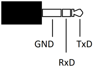
 So I’m stuck here at the moment… So,